Difference between revisions of "8051 Development Board Setup"
| Line 1: | Line 1: | ||
| + | [[Category:8051_tutorials]] | ||
{{box|type=green_dark|text='''Setting up the tools for 8051'''}} | {{box|type=green_dark|text='''Setting up the tools for 8051'''}} | ||
Revision as of 10:58, 26 March 2014
Contents
Introduction
There are various software and hardware tools required to get started with the 8051 micrcontroller. In this tutorial we will discuss, how you can set them up and get going.
Software Tools
Following software tools are required before proceeding with the 8051 tutorials. 1. Compiler and Integrated Development Environment(IDE): We will be using Kiel in all the tutorials. A Evaluation version of the software can be downloaded here. 2. Programmer Software: Used to transfer hex file from computer to micrcontroller; Flash Magic, can be downloaded here
Development Boards
Each of the hardware interfacing tutorials, may require varied hardware setup. We recommend you to choose a platform on which you can test and develop a number of peripheral. From Xplore Labz we recommend you the ULTRA_X51 development board. Or if you're low on budget you could go for STARTER_X51 and request for additional peripherals as required. Having said that you could implement hardware on your own for all the tutorials; only ensure that you've thoroughly verified the schematics with the ones mentioned in the tutorials."
Creating a Project
Assuming you have installed Kiel, let us proceed with creating a project. We have developed a library of commonly used functions for most of the standard peripherals for the 8051 microcontroller family. This will be required in most of the tutorials. We would be required to import the required library files in each of the tutorials.It can be downloaded here Hence you could refer to the step by step procedure below:
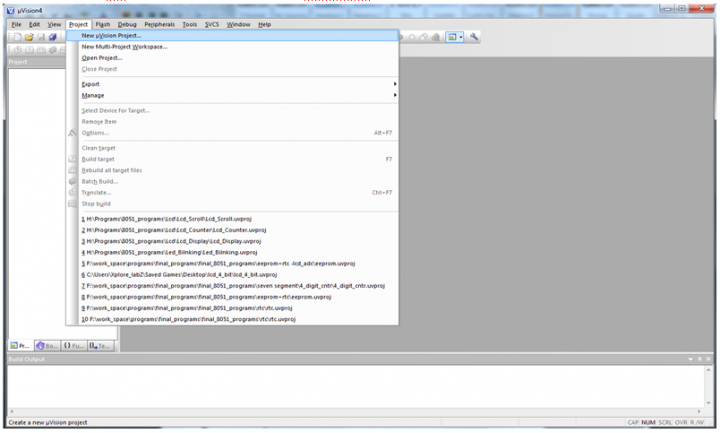
Step 1: Open the Keil software and select the New Microvision project from Project Menu as shown below.
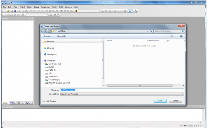
Step 2: Browse to your project folder and provide the project name and click on save.
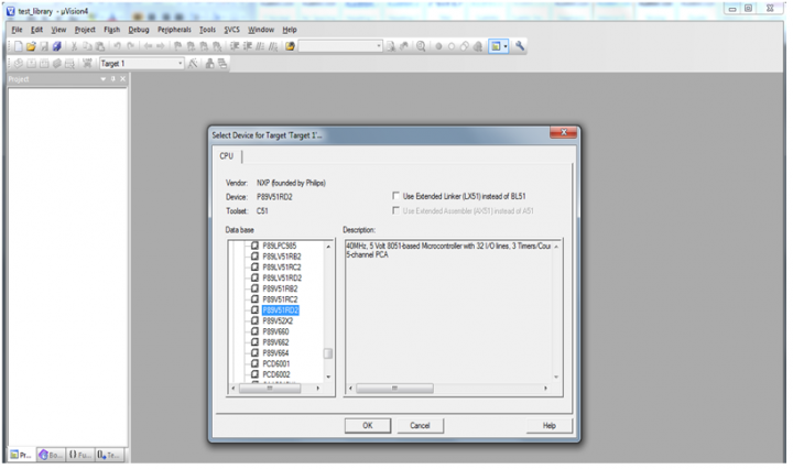
Step 3: Once the project is saved a new dialog box “Select Device for Target” opens, Select the controller(Atmel:At89s52/NXP:P89v51rd2) and click on OK.
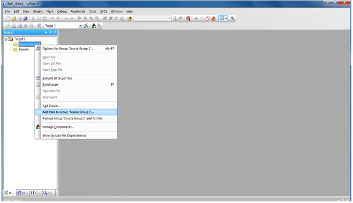
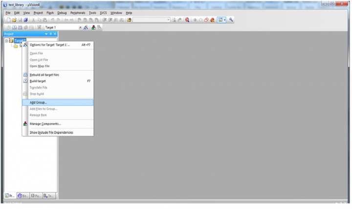
Step 4: Once the project is created add a new header group to include the library header files.
Step 5: Add the library files to the project .c files to Source group and .h files to header group.<br\> Note:
- Copy the library files into the project folder before including them into the project.
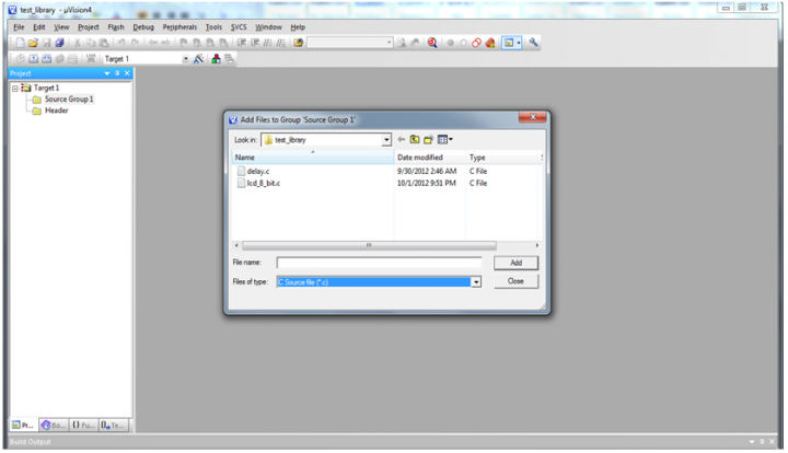
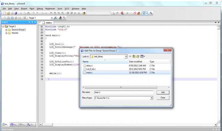
Step 6: Add the .c files by selecting “C Source files” from “Files of type drop down”.
Step 7: Add the header( .h) files by selecting “Text file(.txt, .h, .inc)” from “Files of type” drop down.
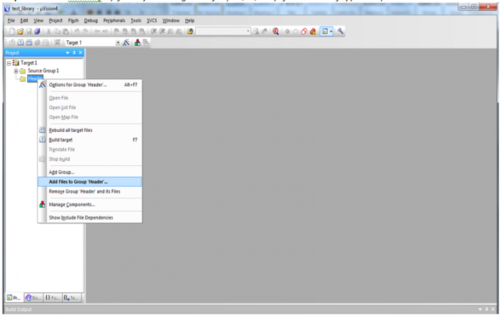
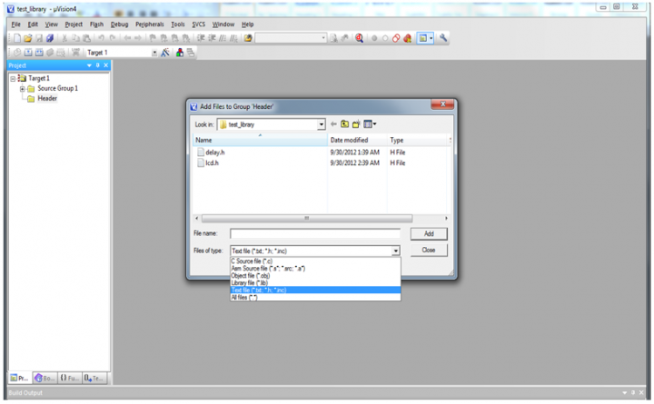
Step 8: After including the library files, create a new .c file to write the main program.
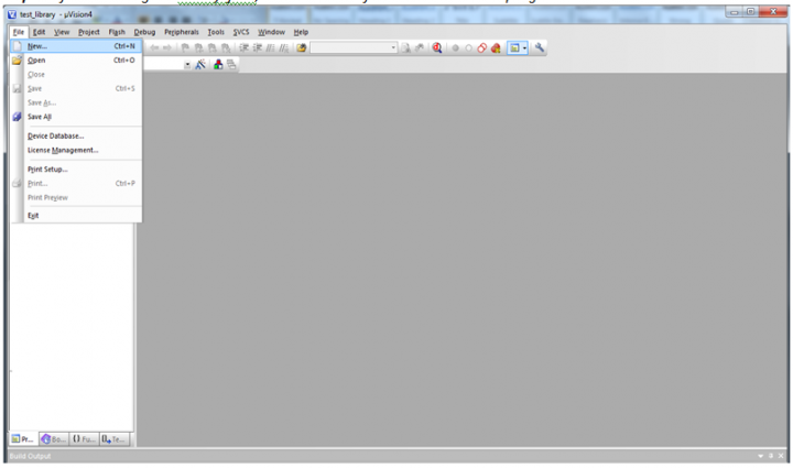
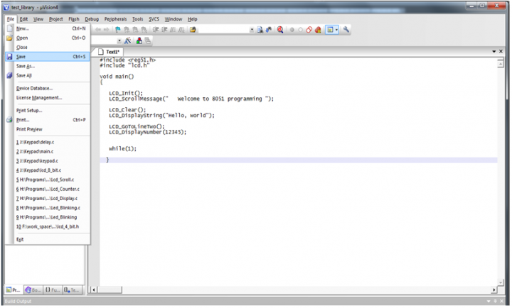
Step 9: Write your program using the library functions and save it.<br\> Note:
- Include the respective header files before calling any library functions.
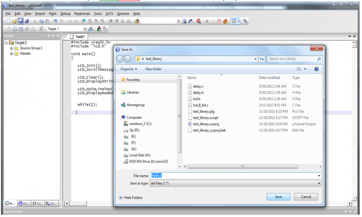
Step 10: Provide the suitable file name(main.c) and save it in the same project folder.
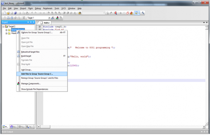
Step 11: Include your source file to the project.
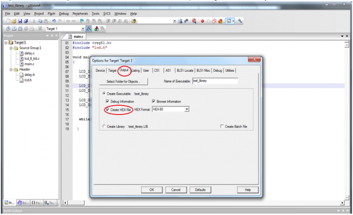
Step 12: Configure the project to generate the hex file after compilation.
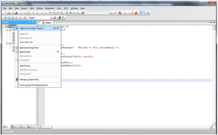
Step 13: Select the output menu and check the Create Hex File option to generate the hex file.
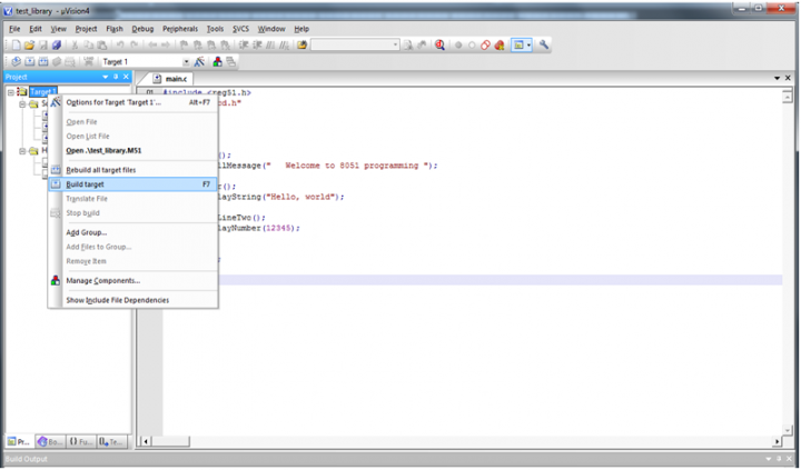
Step 14: Compile the project by clicking on Build target (or press F7). Project complies if there are no errors. If there are any errors fix them and re-compile.
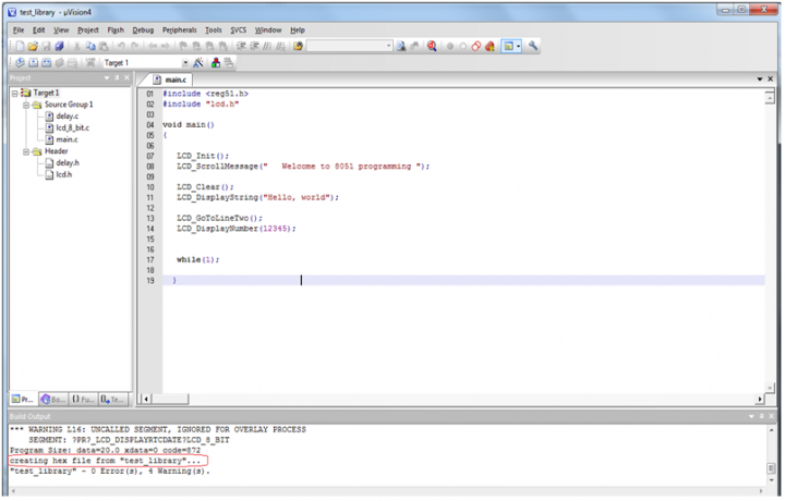
Step 15: Once the project is built(compiled), hex file will be generated with the message as shown below. If the hex file is not generated then follow Step 12.
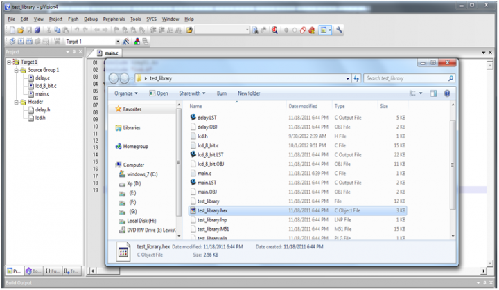
Step 16: Hex file will be generated with the project name in the selected project folder.
Transferring the hex file to microcontroller with flash magic
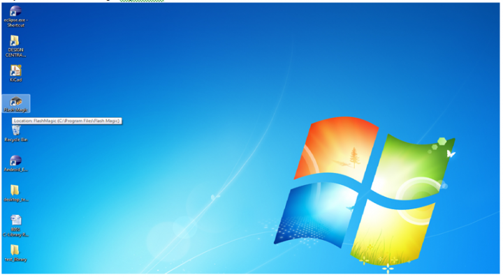
Step 1: Run the Flash magic Software .
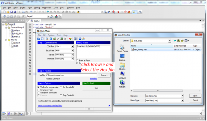
Step 2:
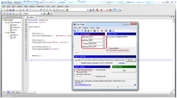
- a. Select the Com port to which the controller(targed board) is connected.
- b. Configure the baud rate as 4800/7200/19200 etc. from drop down. (9600 is recommended).
- c. Select the device as 89V51RD2 from the Device drop down menu.
- d. Select None ISP mode from Interface menu
- e. Check the option Erase blocks used by Hex File.
- f. Check the option Verify the after programming.
Step 3: Browse and select the hex file to be flashed into the controller.
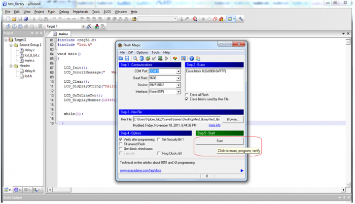
Step 4: Click on Start to flash the hex file into the controller. It is recommeded to Hold the reset botton before clicking the start button of flash magic.
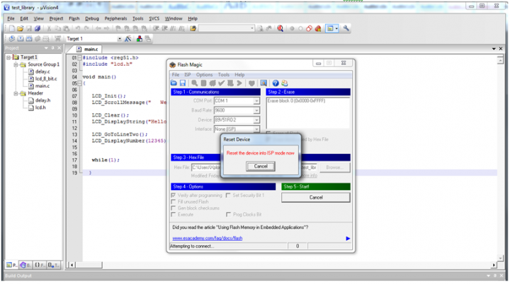
Step 5: Once the start button is clicked a message pops up asking to rest the device, now reset the device.If the below message is not displayed then double check the ComPort Connection, Max232 or reduce the baudrate.If still the problem persist then Turn OFF the board, Click on start button and now Turn ON the board.
Step 6: Flash magic starts programming the controller. Do not disturb the connection or Power Off while the controller is being programmed.
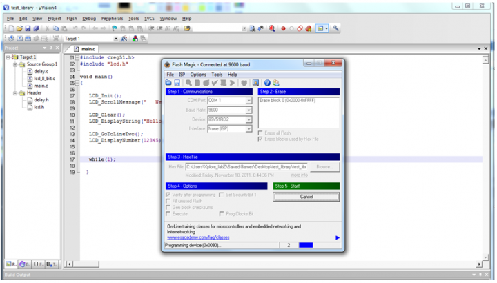
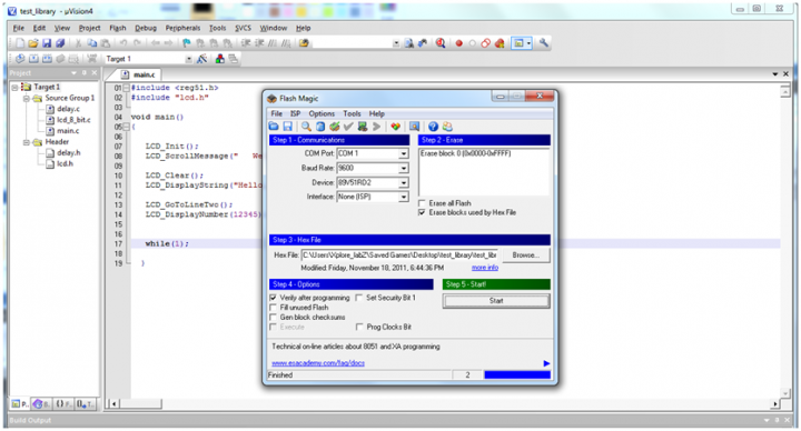
Step 7: Once the hex file is successfully programmed, Reset the controller to run the Program.
{{#seo: |title=8051_ToolsSetup |titlemode=append |keywords=8051,AT89s51,at89c51,p89v51rd2,XploreLabz,8051 Software Tools,8051 Development Boards,Burning Hex File,Flashing Hex File,Flash Magic,Keil |description= 8051 ToolsSetup }}
Would like to have your feedback and suggestions here;

