7.8051 Interfacing:LEDs (Redirected from LED Interfacing with 8051)
Contents
Introduction
Light Emitting Diodes as we know are PN Junction diodes which emit light when forward biased. Well, lets say they simply emit light! They come in various packages through hole as well as SMD. They are basically used to:
- Indicate System status, ON/OFF etc.
- LED lighting: Well, recent technology trends show a increasing usage of LEDs in domestic and industrial lighting. And there are cool projects in DIY community too. Check the Lumapad for instance.
- Also you could build some display projects like the persistence of vision[POV].
Well, lets just start interfacing a simple LED with the micrcontroller.
Objective
Turn ON LEDs for a second, and turn OFF LEDs for a second repeatedly. The LEDs are connected to any of the four ports of the 8051 microcontroller.
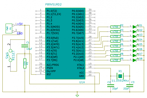
Schematic Diagram
Bare Minimum
To make a micrcontroller work, following components are required:
- Clock Source: It is provided by a crystal oscillator and two capacitors as shown in the schematic.
- Power supply: A +5V power source is required. It could be using a battery or a simple regulated power supply.
- Reset Circuitry: The reset pin should be tied to ground. The microcontroller resets when RST pin has 5v. In the circuit shown above, whenever a switch is pressed, the controller resets.
LED Interface
As we know, providing a logic 1(5v) from microcontroller pin to the anode of the LED, keeping common ground, glows the LED.
The 5mm Led used in this tutorial has a forward voltage of 2v and maximum current rating of 20mA. The microcontroller provides a 5V output on a port pin, hence to limit the current to 10mA a resistance of 470Ω is used in series with the LED.
8 LEDs are interfaced to PORT2 of the schematic as shown. You may wish to connect to any of the other ports as well. You may wish to go for a simple development board ULTRA_X51, which has a inbuilt power supply and serial communication circuitry required to transfer the hex file to the microcontroller. This would get you off the ground quickly.
Code
The code is divided mainly in to two sections for all the interfaces.
- C files
- The c files primarily contain, the main.c and other '*.c' files depending on the peripheral or control features used.
- Header files
- The header files will contain function prototypes of the included c files.
This makes the code reusable. Whenever a interface, or feature is required to be tested, a source file(e.g lcd.c) and a corresponding header(.h) file is included.
So, lets start with a simple example. The entire project can be downloaded from the link at the end of the page. You could view a step by step procedure to configure the project in the 8051 tools set up tutorial.
Led_Blinking.c
The code below is included in Led_Blinking.c file. This file contains the main() function with which execution of the code begins. Lets look at the first two lines of the code
#include <reg51.h>
#include "delay.h"
- #include <reg51.h> contains definitions of all the ports, registers and Special function registers of the 8051 family. This helps the compiler to associate the name of ports and registers used in the c code to their addresses.
- #include "delay.h" This is the delay library file. It generates specified delay in microsecond, milliseconds and seconds.
Then we define LedOn and LedOff as two constants. LedOn sets all the 8 bits and LedOff clears all the 8 bits.
- The main function contains a while(1) function. The argument 1 to function which is always true, hence the loop never ends!
- In the first set of instructions turns ON all leds connected the four ports, for a second and next set turns them OFF, for a second. And this repeats forever!
/* Reg51.h contains the defnition of all ports and SFRs */
#include <reg51.h>
#include "delay.h"
#define LedOn 0xFF	//sending a logic one turns on the LED
#define LedOff 0x00	//sending logic zero turns it off
/* start the main program */
void main()
{
  while(1)
    {
	 /* Turn On all the leds and wait for one second */
	   P0=LedOn;
	   P1=LedOn;
	   P2=LedOn;
	   P3=LedOn;
	   delay_sec(1);
	 /* Turn off all the leds and wait for one second */
	   P0=LedOff;
	   P1=LedOff;
	   P2=LedOff;
	   P3=LedOff;
	   delay_sec(1);
     }
}
delay.c Library file
As discussed earlier, the delay.c contains functions to generate the required delay. It can be accessed here.
{{#seo: |title=LED_Interfacing_With_8051 |titlemode=append |keywords=8051,AT89s51,at89c51,p89v51rd2,XploreLabz,8051 Bare Minimum,LED Interface,LED blinking,Delay.c library file |description= LED Interfacing with 8051 }}
Would like to have your feedback and suggestions here;


