
Difference between revisions of "Keil Setup For 8051"
m (Sandeep moved page 8051 SevenSegment Interface to 9.8051 Interfacing:Seven Segments) |
|||
| Line 40: | Line 40: | ||
void main() | void main() | ||
{ | { | ||
| − | + | unsigned char seg_code[]={0xfc,0x60,0xda,0xf2,0x66,0xb7,0xbe, 0x30,0xfe,0xf6,0xee,0xfe,0x9c,0xfc,0x9e,0x70}; | |
| − | + | ||
| − | + | ||
unsigned char cnt=0; | unsigned char cnt=0; | ||
while(1) | while(1) | ||
Revision as of 11:08, 11 July 2014
Contents
Seven Segment Display


Well, the name 7 segments implies there are 7 LED segments arranged as shown in figure 1. After LEDs they are the easiest interfaces to a microcontroller. There is also a decimal point or dp. It is used when decimal digits like 5.1 etc are displayed.
Applications
Seven segment are widely used in applications where digits[0-9] are required to be displayed.Although they also display letters A to F as shown in figure(2) simulation. This is a very simple and convenient way to display numbers in a bright fashion.
Form Factor
- Sizes:They come in various sizes; 0.28”, 0.3”, 0.32”, 0.36”, 0.39”, 0.4”, 0.5”, 0.56”, 0.6”, 0.8”, 1.0”, 1.2”, 1.5”, 1.8”, 2.0”, 2.3”, 3.0”, 4.0”, 5.0”, 7.0”)
- Colors: and varied colors too; Red, Green, Yellow, Orange, Blue, and White.
Working


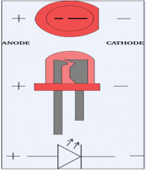
Since these are basically LEDs arranged as a group they can either have anode in common or cathode.
- Common Cathode: This type of 7 segments, requires a positive voltage(5v) to given to the segments a to g in order to glow. This is shown in figure(3). Providing a positive voltage with respect to common cathode makes the LED forward biased.
- Common Anode: This type of 7 segments, requires a negativevoltage(GND) to given to the segments a to g in order to glow. This is shown in figure(4). A ground connection to cathode with respect to common anode again forward biases the LED which glows.
Interfacing 7 segment display to 8051
Driving the Seven Segment
Schematic Diagram

Code
#include <reg51.h>
#include "delay.h"
#define SegmentValue P0
#define SegmentSelection P1
#define SegOne 0x01
#define SegTwo 0x02
#define SegThree 0x04
#define SegFour 0x08
/* start the main program */
void main()
{
unsigned char seg_code[]={0xfc,0x60,0xda,0xf2,0x66,0xb7,0xbe, 0x30,0xfe,0xf6,0xee,0xfe,0x9c,0xfc,0x9e,0x70};
unsigned char cnt=0;
while(1)
{
for(cnt=0x00;cnt<=0x0f;cnt++) // loop to display 0-F
{
SegmentSelection = SegOne; // Select segment
SegmentValue= seg_code[cnt]; // Send code
delay_sec(1);
}
}
}
{{#seo: |title=8051_SevenSegment_Interface |titlemode=append |keywords=8051,AT89s51,at89c51,p89v51rd2,XploreLabz,Interface,Seven Segment Display,Seven segment Applications,Seven segment Form Factor,Interfacing 7 segment display with 8051,Driving Seven Segment,Schematic 7 segment,7 segment,seven segment |description=8051 SevenSegment Interface }}
Would like to have your feedback and suggestions here;