Difference between revisions of "A4.8051 Communication Protocols:UART, RS232"
| Line 1: | Line 1: | ||
| − | {{#setmainimage: | + | [[File:{{#setmainimage: Serial Communication.jpg}}|thumbnail]] |
=UART Serial communication using 8051= | =UART Serial communication using 8051= | ||
{{Box|type=l_green_light|text= | {{Box|type=l_green_light|text= | ||
Revision as of 18:45, 28 December 2013
UART Serial communication using 8051
The basics
There are two ways to connect a microcontroller to a computer.
- Using RS232 protocol to the legacy serial port.
- Using a USB to serial convertor.
From microcontroller programming point of view, there is fundamentally no difference. The communication between the computer and micrcontroller is asynchronous and full duplex.
- Asynchronous: There is no fixed clock to synchronize transmission of data; rather a fix bit rate is specified at both transmitter and receiver, termed as Baud Rate. In simple words, it specifies number of bit received/transmitted in 1 second. With that transmitter and receiver get to know time duration for each bit transfer.
- Full DuplexBoth computer and micrcontroller have the hardware capability to transmit and receive at the same time.
The protocol
RS232:It is a legacy standard for serial communication. The standard defines the electrical characteristics and timing of signals, the meaning of signals, and the physical size and pin-out of connectors.
RS232 Signals
There are various signal for handshaking and communication in RS232 protocol. These are hardly used with modern computers, hence we will see Transmit(Tx) and Receive(Rx) Signals only.
Voltage Levels
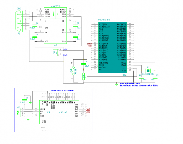
Table below shows the voltage levels for RS232. They are significantly different from the TTL high(5v) and Low(0v). Hence a line driver like the MAX232 is required as shown in the schematic.
| Logic level | Voltages(V) |
|---|---|
| 0 | +3 to +25V |
| 1 | -3 to -25V |
| Z | +3 to -3V |
8051 Serial communication Registers
SBUFF: Serial buffer register
- SBUFF, it is a serial buffer for data. It holds 8 bit data that needs to be transmitted or the data that is received. Since the serial port of 8051 is full duplex, the microcontroller internally manages to transmit and receive data into the buffer register simultaneously.
| SBUFF | |||||||
|---|---|---|---|---|---|---|---|
| D7 | D6 | D5 | D4 | D3 | D2 | D1 | D0 |
SCON: Serial Control Register
| SCON | |||||||
|---|---|---|---|---|---|---|---|
| D7 | D6 | D5 | D4 | D3 | D2 | D1 | D0 |
| SM0 | SM1 | SM2 | REN | TB8 | RB8 | TI | RI |
- SM0 - Serial port mode bit 0 is used for serial port mode selection.
- SM1 - Serial port mode bit 1.
| SM0 | SM1 | Operation | Description | Baud Rate Source |
|---|---|---|---|---|
| 0 | 0 | Mode 0 | 8bit ShiftReg | 1/12 the quartz frequency |
| 0 | 1 | Mode 1 | 8 bit UART | Determined by the timer 1 |
| 1 | 0 | Mode 2 | 9 bit UART | 1/32 the quartz frequency |
| 1 | 1 | Mode 0 | 9 bit UART | Determined by the timer 1 |
- SM2 - Serial port mode 2 bit, also known as multiprocessor communication enable bit. When set, it enables multiprocessor communication in mode 2 and 3, and eventually mode 1. It should be cleared in mode 0.
- REN - Reception Enable bit enables serial reception when set. When cleared, serial reception is disabled.
- TB8 - Transmitter bit 8. Since all registers are 8-bit wide, this bit solves the problem of transmitting the 9th bit in modes 2 and 3. It is set to transmit a logic 1 in the 9th bit.
- RB8 - Receiver bit 8 or the 9th bit received in modes 2 and 3. Cleared by hardware if 9th bit received is a logic 0. Set by hardware if 9th bit received is a logic 1.
- TI - Transmit Interrupt flag is automatically set at the moment the last bit of one byte is sent. It's a signal to the processor that the line is available for a new byte transmit. It must be cleared from within the software.
- RI - Receive Interrupt flag is automatically set upon one byte receive. It signals that byte is received and should be read quickly prior to being replaced by a new data. This bit is also cleared from within the software.
The Baud Rate
As discussed earlier, both transmitter and receiver should agree upon a fixed data transfer rate known as baud rate. For the 8051 the Timer 1' is used to generate the baud rate in Auto reload mode.
The crystal frequency Fclk is divided by 12 internally which is used to execute instructions also known as Machine Clock. Mclk. The timer again divides the Mclk by 32 and uses it as timer frequecny, say Tclk.
Usually a 11.0592 Mhz crystal oscillator is used to provide clock to 8051. The value seems to be odd but we see how it makes sense.
From above discussion
Mclk = Fclk / 12 = 11.0592MHz/12 = 921.6KHz
Tclk = Mclk/32= 921.6KHz/32 = 28.8KHz <br\>
If we look at the standard baud rates used for serial communication shown in the table below, we can observe that all the baud rates are factors or multiples of the Tclk (28.8K)! This results in low error rates and hence is a commonly used crystal with 8051.
| Baud Rate | Multiple (or Factor) |
|---|---|
| 2400 | Tclk/12 |
| 4800 | Tclk/6 |
| 9600 | Tclk/3 |
| 115200 | Tclk*4 |
| 14400 | Tclk*5 |
The Schematic
The Code
main.c
#include <reg51.h>

#include "uart.h"	//Xplore Labz UART library

/* start the main program */
void main()
{
    char msg[50];
    UART_Init(); // function to initialzie UART

   while(1)
    {

	 UART_TxString("\n\n\rEnter a new String: ");
	 UART_RxString(msg);
         UART_TxString("\n\rEntered String: ");
         UART_TxString(msg); //Transmit the received string
     }

}
Basic functions uart.c
void UART_Init()
{
      TMOD |=0x20; //Timer1 in Mode2.
      TH1=-3;    // 9600 Baud rate at 11.0592MHz
      SCON=0x50; // Asynchronous mode 8-bit data and 1-stop bit
      TR1=1;     //Turn ON the timer.
}
This function initializes the UART module in 8051.
- Timer 1 is setup in 8-bit auto reload mode as discussed
earlier
- To get the baud rate of 9600 at 11.0592MHz crystal, we can see from the baud rate table that it requires a factor of three. Hence TH1 is loaded with -3 so that 28.8KHz is divided by 3 to get the exact baud rate.
- SCON is configured in widely used mode :Asynchronous mode 8-bit data and 1-stop bit
- The timer is turned on.
<br\> UART_RxChar() The RI interrupt flag sets as soon as data is received. The function waits till that happens, reads bytes and clears flag.
char UART_RxChar()
{
  while(RI==0);	  // Wait till the data is received
  RI=0;        // Clear Receive Interrupt Flag for next cycle
  return(SBUF);	  // return the received char
}
<br\> UART_TxChar() The character to be transmitted is loaded in buffer, and the function waits till it transmitted by checking the TI flag.
void UART_TxChar(char ch)
{
    SBUF=ch;	   // Load the data to be transmitted
    while(TI==0);    // Wait till the data is trasmitted
     TI=0;		   //Clear the flag for next cycle.
}
The UART_TxString() and UART_RxString() functions use UART_TxChar() and UART_RxChar() as building blocks.
Download
The download does not just contain the example discussed, it also has several other examples that you may go through!
{{#widget:Facebook_Like_Box|profile=http://www.facebook.com/XploreLabz}}
Have a opinion, suggestion, feedback or question about the tutorial, please comment below!


