Difference between revisions of "PIC16F877A ADC on Starter Borad"
| Line 1: | Line 1: | ||
[[Category:Starter PIC16F877]] | [[Category:Starter PIC16F877]] | ||
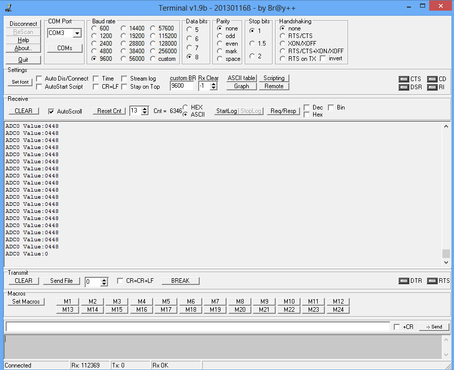
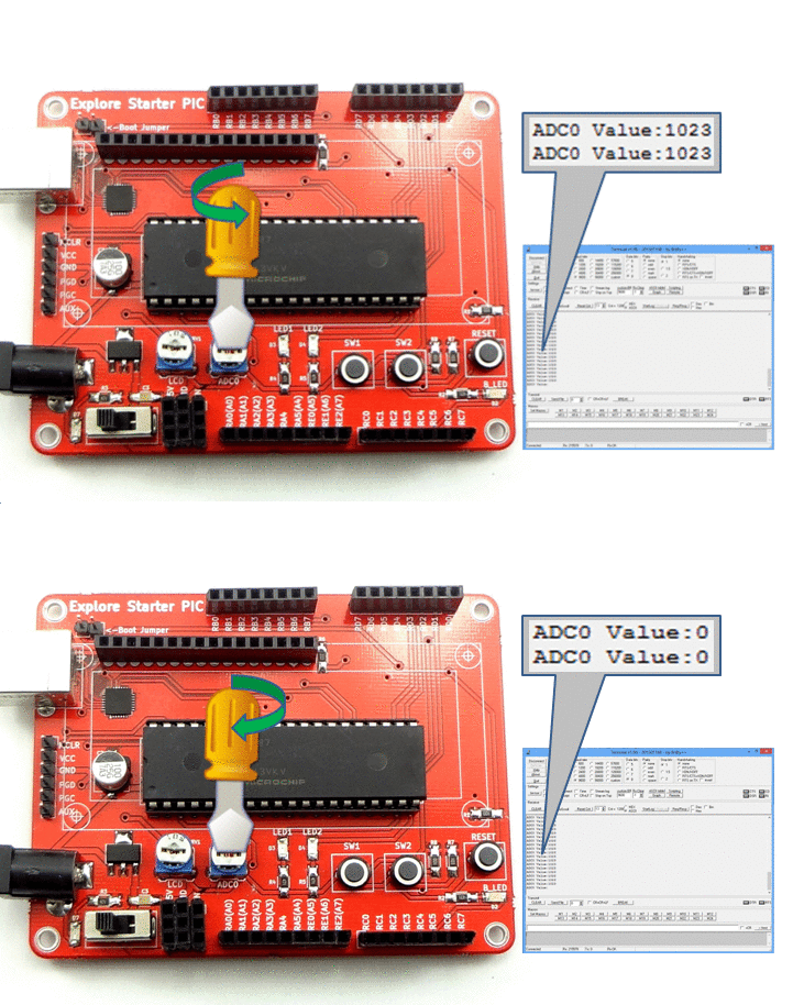
| + | In this tutorial we will see how to read the ADC values on PIC16f877A starter board.<br> | ||
| + | Starter board comes with on board POT connected to ADC0, same POT value will be read and transmitted on UART at 9600 baudrate. | ||
| + | <br><br> | ||
| + | |||
| + | =PIC16F877A ADC pins= | ||
| + | PIC16F877A has inbuilt 8channel 10-bit ADC. Below tables shows the ADC pin mapping.<br> | ||
| + | {| class="table table-striped table-hover table-condensed table-bordered" | ||
| + | |-class="info" | ||
| + | !Adc Channel || Pic16f877a Pin | ||
| + | |- | ||
| + | |0|| PA.0 | ||
| + | |- | ||
| + | |1|| PA.1 | ||
| + | |- | ||
| + | |2|| PA.2 | ||
| + | |- | ||
| + | |3|| PA.3 | ||
| + | |- | ||
| + | |4|| PA.5 | ||
| + | |- | ||
| + | |2|| PE.0 | ||
| + | |- | ||
| + | |3|| PE.1 | ||
| + | |- | ||
| + | |4|| PE.2 | ||
| + | |}<br><br> | ||
=Code= | =Code= | ||
Revision as of 18:53, 2 May 2016
In this tutorial we will see how to read the ADC values on PIC16f877A starter board.
Starter board comes with on board POT connected to ADC0, same POT value will be read and transmitted on UART at 9600 baudrate.
PIC16F877A ADC pins
PIC16F877A has inbuilt 8channel 10-bit ADC. Below tables shows the ADC pin mapping.
| Adc Channel | Pic16f877a Pin |
|---|---|
| 0 | PA.0 |
| 1 | PA.1 |
| 2 | PA.2 |
| 3 | PA.3 |
| 4 | PA.5 |
| 2 | PE.0 |
| 3 | PE.1 |
| 4 | PE.2 |
Code


