
Difference between revisions of "Interfacing Seven Segment Displays with AVR"
| Line 1: | Line 1: | ||
[[Category:AVR Tutorials]] | [[Category:AVR Tutorials]] | ||
| − | [ | + | In this tutorial we will looking at interfacing a '''Seven Segment Display''' to Atmega32 MCU. We will also look at multiplexing 4 seven segment displays and programming them. |
| + | =Seven Segment Display= | ||
| + | [[File:BasicSevenSegmentDisplay.png|thumbnail|fig 1: Basic 7 segment Display]] | ||
| + | [[File:7 segments Indicator.gif|framed|fig 2: Simulation]] | ||
| + | Well, the name 7 segments implies there are 7 LED segments arranged as shown in figure 1. | ||
| + | After LEDs they are the easiest interfaces to a microcontroller. | ||
| + | There is also a decimal point or dp. It is used when decimal digits like 5.1 etc are displayed. | ||
| + | ==Applications== | ||
| + | Seven segment are widely used in applications where digits[0-9] are required to be displayed.Although they also display letters A to F as shown in figure(2) simulation. | ||
| + | This is a very simple and convenient way to display numbers in a bright fashion. | ||
| + | ==Form Factor== | ||
| + | |||
| + | *'''Sizes''':They come in various sizes; 0.28”, 0.3”, 0.32”, 0.36”, 0.39”, 0.4”, 0.5”, 0.56”, 0.6”, 0.8”, 1.0”, 1.2”, 1.5”, 1.8”, 2.0”, 2.3”, 3.0”, 4.0”, 5.0”, 7.0”) | ||
| + | *'''Colors''': and varied colors too; Red, Green, Yellow, Orange, Blue, and White. | ||
| + | ==Working== | ||
| + | [[File:Common Cathode 7Segment.jpeg|thumbnail|fig 3:Common Cathode Display]] | ||
| + | [[File:Common Anode 7Segment.jpeg|thumbnail|fig 4: Common Anode 7 segment]] | ||
| + | Since these are basically LEDs arranged as a group they can either have anode in common or cathode. | ||
| + | *'''Common Cathode''': This type of 7 segments, requires a positive voltage(5v) to given to the segments '''a''' to '''g''' in order to glow. This is shown in figure(3). Providing a positive voltage with respect to common cathode makes the LED forward biased. | ||
| + | *'''Common Anode''': This type of 7 segments, requires a negativevoltage(GND) to given to the segments '''a''' to '''g''' in order to glow. This is shown in figure(4). A ground connection to cathode with respect to common anode again forward biases the LED which glows.<br /> | ||
| + | |||
| + | =Interfacing Single Seven Segment Display= | ||
| + | ==Schematic== | ||
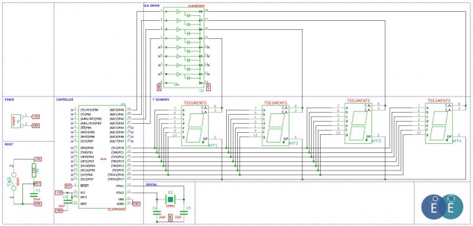
| + | The seven segment is interfaced as shown in the schematic below. Notice that sending a '''logic one''' to segments '''a to g''' will turn them ON. With that we can create a sequence. | ||
[[File:Schematic AVR Interfacing 7Segment.JPG|680px]] | [[File:Schematic AVR Interfacing 7Segment.JPG|680px]] | ||
Revision as of 12:02, 29 October 2014
In this tutorial we will looking at interfacing a Seven Segment Display to Atmega32 MCU. We will also look at multiplexing 4 seven segment displays and programming them.
Contents
Seven Segment Display


Well, the name 7 segments implies there are 7 LED segments arranged as shown in figure 1. After LEDs they are the easiest interfaces to a microcontroller. There is also a decimal point or dp. It is used when decimal digits like 5.1 etc are displayed.
Applications
Seven segment are widely used in applications where digits[0-9] are required to be displayed.Although they also display letters A to F as shown in figure(2) simulation. This is a very simple and convenient way to display numbers in a bright fashion.
Form Factor
- Sizes:They come in various sizes; 0.28”, 0.3”, 0.32”, 0.36”, 0.39”, 0.4”, 0.5”, 0.56”, 0.6”, 0.8”, 1.0”, 1.2”, 1.5”, 1.8”, 2.0”, 2.3”, 3.0”, 4.0”, 5.0”, 7.0”)
- Colors: and varied colors too; Red, Green, Yellow, Orange, Blue, and White.
Working


Since these are basically LEDs arranged as a group they can either have anode in common or cathode.
- Common Cathode: This type of 7 segments, requires a positive voltage(5v) to given to the segments a to g in order to glow. This is shown in figure(3). Providing a positive voltage with respect to common cathode makes the LED forward biased.
- Common Anode: This type of 7 segments, requires a negativevoltage(GND) to given to the segments a to g in order to glow. This is shown in figure(4). A ground connection to cathode with respect to common anode again forward biases the LED which glows.
Interfacing Single Seven Segment Display
Schematic
The seven segment is interfaced as shown in the schematic below. Notice that sending a logic one to segments a to g will turn them ON. With that we can create a sequence.


Code and explanation will be updated soon..