Interactive Menus for your project with a Display and an Encoder Revision as of 15:54, 2 August 2016 by Raghavendra (Talk | contribs)
Ever wondered about how simple an User Interface (UI) for your next electronics hack or project be? Indeed, and you should also seen the humble rotary encoder and a Display as UI for 3D printer or other gadgets. In this tutorial we will look at building such a system with a Nokia 5110 display and a rotary encoder KY-040.
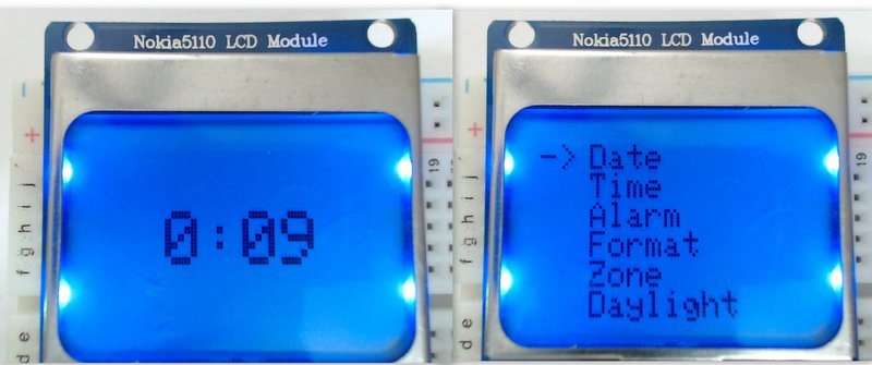
You may use any other character or graphics displays as well as other encoder models. Instead making the code generic, we will start building an UI for a digital clock. On it's home screen it will show time. The pushing of the select switch on the encoder will display the Menu. The Menu in turn will have numerous setting for time, date, time format (12 Hour vs 24 Hour ), time Zone etc..,
Hookup
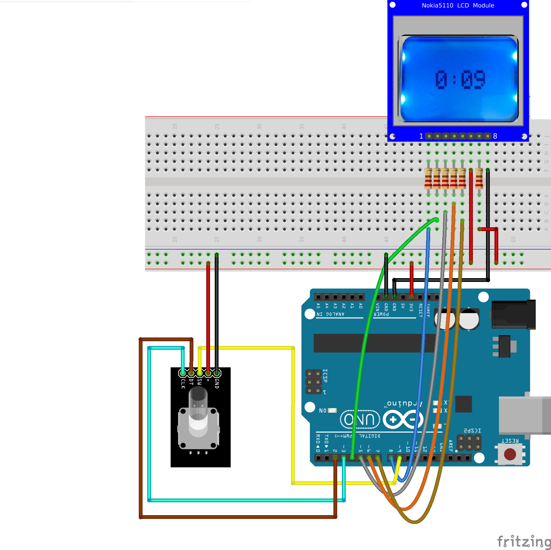
The basic hookup will remain same during the entire tutorial. We will test the encoder first and then the display. You may want to hook-up all the things at once or do it step by step. The encoder first and then the display. I would recommend doing it step by step.
Encoder Basics
Encoders are great input devices which have infinite travel in both clockwise(CW) and anti-clockwise directions(CCW). What that essentially means is that the input range for your gizmo can be decided in software. As in case of your clock, the user may have to transverse a menu of say 8 items. The range for the Menu will be 0 to 7 in both directions . However to input time from the user, the hours will be (0 to 23), minutes and seconds will be (0 to 60). Encoders will help us do all of the above. Apart from this the encoder we will be using also has a select switch. Which can be used to select menu items or confirm an action.
I would highly recommend you to go through the Improved Arduino Rotary Encoder Reading instructable to understand the types of encoders, the internal mechanism and all the related terminology.
I started out with hooking up just the encoder with Arduino and printing the message on the terminal. The code is brilliantly written. It simply increments a variable called encoderPos if the encoder is turned CW and decremented if turned CCW.
The code uses to Interrupt pins 2 and 3 on Arduino. These are setup to trigger on a rising edge of the pulse. The interrupts trigger functions PinA() and PinB() for interrupts on pins 2 and 3 respectively which eventually result in decremented or increment the count. Since these are interrupt functions these aren't called anywhere in the setup() and loop() functions. Also notice the use of keyword volatile for the variables used in the Interrupt functions. We will cover more on interrupts in some other tutorial. However note that this code will only work if the pins 2 and 3 are used. Because other pins on Atmega328 will not have interrupt handling capability.
The code below is all that is required to read the encoder position as well as the select switch.
| /*******Interrupt-based Rotary Encoder Sketch******* | |
| by Simon Merrett, based on insight from Oleg Mazurov, Nick Gammon, rt, Steve Spence | |
| modified at EE to include the select switch | |
| Tutorial at: | |
| http://exploreembedded.com/wiki/Interactive_Menus_for_your_project_with_a_Display_and_an_Encoder | |
| */ | |
| static int pinA = 2; // Our first hardware interrupt pin is digital pin 2 | |
| static int pinB = 3; // Our second hardware interrupt pin is digital pin 3 | |
| static int selectSwitch = 9; //The select switch for our encoder. | |
| volatile byte aFlag = 0; // let's us know when we're expecting a rising edge on pinA to signal that the encoder has arrived at a detent | |
| volatile byte bFlag = 0; // let's us know when we're expecting a rising edge on pinB to signal that the encoder has arrived at a detent (opposite direction to when aFlag is set) | |
| volatile uint16_t encoderPos = 0; //this variable stores our current value of encoder position. Change to int or uin16_t instead of byte if you want to record a larger range than 0-255 | |
| volatile uint16_t oldEncPos = 0; //stores the last encoder position value so we can compare to the current reading and see if it has changed (so we know when to print to the serial monitor) | |
| volatile byte reading = 0; //somewhere to store the direct values we read from our interrupt pins before checking to see if we have moved a whole detent | |
| void setup() { | |
| pinMode(pinA, INPUT_PULLUP); // set pinA as an input, pulled HIGH to the logic voltage (5V or 3.3V for most cases) | |
| pinMode(pinB, INPUT_PULLUP); // set pinB as an input, pulled HIGH to the logic voltage (5V or 3.3V for most cases) | |
| pinMode(selectSwitch, INPUT_PULLUP); | |
| attachInterrupt(0,PinA,RISING); // set an interrupt on PinA, looking for a rising edge signal and executing the "PinA" Interrupt Service Routine (below) | |
| attachInterrupt(1,PinB,RISING); // set an interrupt on PinB, looking for a rising edge signal and executing the "PinB" Interrupt Service Routine (below) | |
| Serial.begin(115200); // start the serial monitor link | |
| } | |
| void PinA(){ | |
| cli(); //stop interrupts happening before we read pin values | |
| reading = PIND & 0xC; // read all eight pin values then strip away all but pinA and pinB's values | |
| if(reading == B00001100 && aFlag) { //check that we have both pins at detent (HIGH) and that we are expecting detent on this pin's rising edge | |
| encoderPos --; //decrement the encoder's position count | |
| bFlag = 0; //reset flags for the next turn | |
| aFlag = 0; //reset flags for the next turn | |
| } | |
| else if (reading == B00000100) bFlag = 1; //signal that we're expecting pinB to signal the transition to detent from free rotation | |
| sei(); //restart interrupts | |
| } | |
| void PinB(){ | |
| cli(); //stop interrupts happening before we read pin values | |
| reading = PIND & 0xC; //read all eight pin values then strip away all but pinA and pinB's values | |
| if (reading == B00001100 && bFlag) { //check that we have both pins at detent (HIGH) and that we are expecting detent on this pin's rising edge | |
| encoderPos ++; //increment the encoder's position count | |
| bFlag = 0; //reset flags for the next turn | |
| aFlag = 0; //reset flags for the next turn | |
| } | |
| else if (reading == B00001000) aFlag = 1; //signal that we're expecting pinA to signal the transition to detent from free rotation | |
| sei(); //restart interrupts | |
| } | |
| void loop(){ | |
| if(oldEncPos != encoderPos) { | |
| Serial.println(encoderPos); | |
| oldEncPos = encoderPos; | |
| } | |
| // The select switch is pulled high, hence the pin goes low if the switch is pressed. | |
| if(digitalRead(selectSwitch)==0) | |
| { | |
| Serial.println("Key Pressed"); | |
| delay(5); // wait for debounce to get over | |
| } | |
| } |
Display Basics
As said earlier I will be using a Nokia 5110 84x48 pixels graphic display for this tutorial. I will be using the well written Adafruit display and graphics libraries. The display is instantiated with the following pins.
- // Software SPI:
- // pin 7 - Serial clock out (SCLK)
- // pin 6 - Serial data out (DIN)
- // pin 5 - Data/Command select (D/C)
- // pin 4 - LCD chip select (CS)
- // pin 8 - LCD reset (RST)
You may use the sample sketch that comes with the library to test if the display is indeed working with the setup.


