
Difference between revisions of "I2C/TWI Basics"
| Line 9: | Line 9: | ||
The Master generates the clock for serial communication | The Master generates the clock for serial communication | ||
| + | |||
| + | =I2C Timings and Conditions.= | ||
| + | Figure below shows the timing diagram for I²C. | ||
| + | [[File:I2C data transfer.png|thumbnail|x100px|Fig: I2C data transfer]] | ||
| + | |||
| + | =Start Condition= | ||
| + | As seen from the timing diagram, a data transfer is initiated with the '''Start(S)''' condition. The start occurs when '''SCL''' is high and '''SDA''' goes from high to low. | ||
| + | |||
| + | |||
| + | |||
| + | |||
| + | |||
}} | }} | ||
Revision as of 14:02, 28 January 2014
It is uses I²C (Inter-Integrated Circuit) protocol, referred to as I-squared-C, I-two-C, or IIC) for communication with the micrcontroller.Let see first the basics of the communication protocol first.
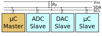
 A sample schematic with one master and three slaves
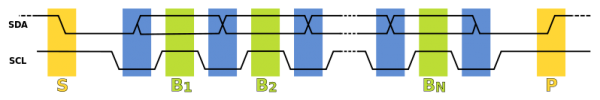 Fig: I2C data transfer

The I²C require only two wires for communication. One is called the Serial Data (SDA) and the other is Serial Clock (SCL) as shown.
There are various modes and configurations in which it can be used. Let us start simply with a single master and a single slave.
The Master generates the clock for serial communication
I2C Timings and Conditions.
Figure below shows the timing diagram for I²C.
Start Condition
As seen from the timing diagram, a data transfer is initiated with the Start(S) condition. The start occurs when SCL is high and SDA goes from high to low.