
Difference between revisions of "Explore Robo"
| Line 77: | Line 77: | ||
=Electronics= | =Electronics= | ||
| + | ==Robo Controller Board== | ||
{{Box|type=l_green_light|text=<br/> | {{Box|type=l_green_light|text=<br/> | ||
*The Robo Board: This is the heart of the robot. The board has following ICs | *The Robo Board: This is the heart of the robot. The board has following ICs | ||
| Line 82: | Line 83: | ||
**'''DTMF Decoder''': A MT8870 or compatible IC is used to convert DTMF mobile tones to digits, which helps in making Mobile controlled Robot | **'''DTMF Decoder''': A MT8870 or compatible IC is used to convert DTMF mobile tones to digits, which helps in making Mobile controlled Robot | ||
**'''Microcontroller''': The board feature a Atmega8 (Atmega328 can also be used) controller. Figure below shows the way in which various units are connected to the microcontroller. | **'''Microcontroller''': The board feature a Atmega8 (Atmega328 can also be used) controller. Figure below shows the way in which various units are connected to the microcontroller. | ||
| − | + | [[File:Explore Robo Pinout.jpg|x430px|framed|Pinout]] | |
}} | }} | ||
| + | ==Sensor Sheild== | ||
=Downloads= | =Downloads= | ||
Revision as of 13:58, 26 August 2014
Hack it like a arduino or build on it like an AVR. Integrated DTMF and Motor driver, will help you build you're next superbot with ease!


.JPG)
.JPG)
.JPG)
Features
- Robotics board based on Atmega8 MCU.
- Sensor shield to make line follower, light follower and obstacle avoidance robot.
- Inbuilt DTMF decoder (MT8870) to make a Mobile controlled Robot
- USB to UART convertor (CP2102) for communicating with computer, make a computer controlled Robot.
- MCU with bootloader, no external programmer required.
- Compatible with Arduino Software.
Package Contains
- Electronics
- Robotics Board Based on Atmega8, with L293D driver and MT8870 DTMF Decoder
- Sensor Sheild for line, light and obstacle detecting robots
- Mechanical
- Chasis(Red and White Basis)
- BO Motor Clamps
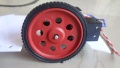
- DC BO Motors 150 RPM
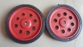
- Wheels x2
- Castor Wheel
- Screws
- Battery Holder x2
- Other
- USB Cable
- 5 Pin Sensor cable
Contents
Mechanical
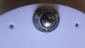
Assembling the Robot
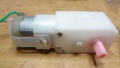
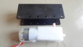
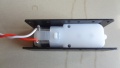
Mounting the BO Motor with Clamps

Attaching BO Clamps to BO Motor
Step 1
Step 2
Step 3
Step 4
Step 5
Step 6


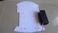
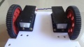
Attaching Wheels to chasis

Step 1
Step 2
Step 3
Step 4


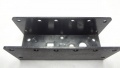
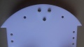
Assembling the Base

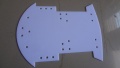
Step 1
Step 2
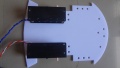
Step 3
Step 4


Electronics
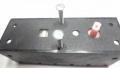
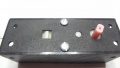
Robo Controller Board
- The Robo Board: This is the heart of the robot. The board has following ICs
- Motor Driver: A L293D Motor driver on board is used to control the two driving motors of the Robot
- DTMF Decoder: A MT8870 or compatible IC is used to convert DTMF mobile tones to digits, which helps in making Mobile controlled Robot
- Microcontroller: The board feature a Atmega8 (Atmega328 can also be used) controller. Figure below shows the way in which various units are connected to the microcontroller.

Pinout