
Difference between revisions of "Explore Robo"
| (37 intermediate revisions by 4 users not shown) | |||
| Line 1: | Line 1: | ||
[[Category:Robotic Kits]] | [[Category:Robotic Kits]] | ||
| − | [[File: | + | {{Popup|type=l|text= |
| − | <gallery> | + | Hack it like a arduino or build on it like an AVR. Integrated DTMF and Motor driver, will help you build you're next superbot with ease! |
| + | }} | ||
| + | [[File:Cart add.png|right|link=https://www.exploreembedded.com/product/Explore%20Robo]] | ||
| + | {{#ev:youtube|aFyaYK5OJYU|680}} | ||
| + | [[File:DSC08839.JPG|680px]] | ||
| + | [[File:DSC01972 copy.jpg|680px]] | ||
| + | [[File:DSC01973 copy.jpg|680px]] | ||
| + | [[File:Explore_Robo Parts.JPG|680px]] | ||
| + | <gallery mode="packed-hover"> | ||
| + | File:DSC08839.JPG| | ||
| + | File:AVR Robo_1.JPG| | ||
File:3d1.JPG| | File:3d1.JPG| | ||
File:3d2.JPG| | File:3d2.JPG| | ||
| + | File:Robot Sensor Board (3).JPG| | ||
| + | File:Robot Sensor Board (4).JPG| | ||
| + | File:Robot Sensor Board (5).JPG| | ||
| + | File:Robot Sensor Board (7).JPG| | ||
</gallery> | </gallery> | ||
| − | {{ | + | {{Box|type=l_green_light|text='''''Features'''''}} |
| − | + | {{Box|type=l_green_light|text=<br/> | |
| + | *Robotics board based on Atmega8 MCU. | ||
| + | *Sensor shield to make '''line follower, light follower and obstacle avoidance robot.''' | ||
| + | *Inbuilt DTMF decoder (MT8870) to make a '''Mobile controlled Robot''' | ||
| + | *USB to UART convertor (CP2102) for communicating with computer, make a '''computer controlled Robot.''' | ||
| + | *MCU with bootloader, '''no''' external programmer required. | ||
| + | *Compatible with Arduino Software. | ||
| + | }} | ||
| + | {{Box|type=l_green_light|text='''''Package Contains'''''}} | ||
| + | {{Box|type=l_green_light|text=<br/> | ||
| + | *Electronics | ||
| + | **Robotics Board Based on Atmega8, with L293D driver and MT8870 DTMF Decoder | ||
| + | **Sensor Sheild for line, light and obstacle detecting robots | ||
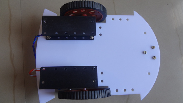
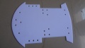
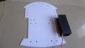
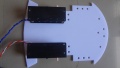
| + | *Mechanical | ||
| + | **Chasis(Red and White Basis) | ||
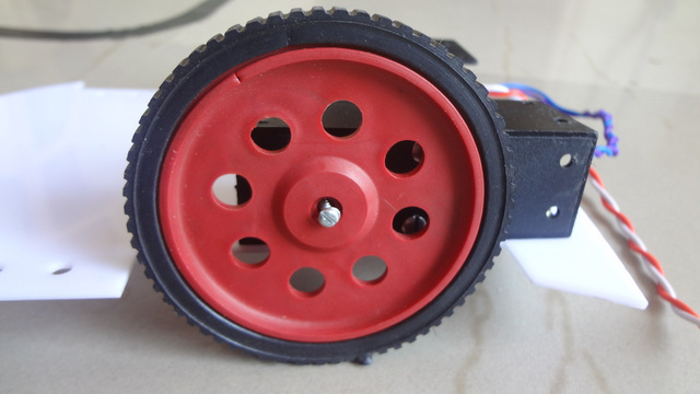
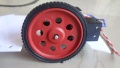
| + | **BO Motor Clamps | ||
| + | **DC BO Motors 150 RPM | ||
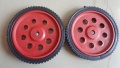
| + | **Wheels x2 | ||
| + | **Castor Wheel | ||
| + | **Screws | ||
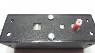
| + | **Battery Holder x2 | ||
| + | *Other | ||
| + | **USB Cable | ||
| + | **5 Pin Sensor cable | ||
}} | }} | ||
| − | |||
| − | |||
| − | |||
| − | |||
| − | + | =Mechanical= | |
| − | + | ==Assembling the Robot== | |
| − | + | ===Quick Video=== | |
| − | + | {{#ev:youtube|AYSAGtPI3KU|600}} | |
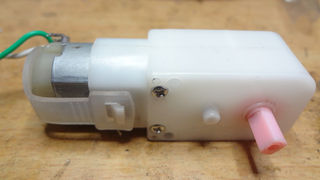
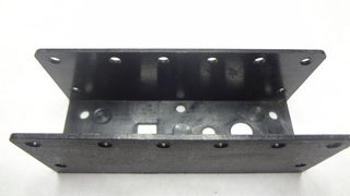
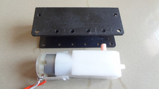
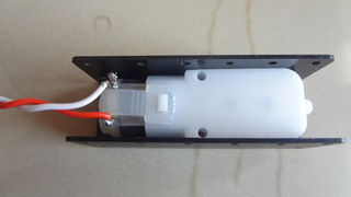
| − | + | ===Mounting the BO Motor with Clamps=== | |
| − | + | [[File:Robo Wheel mouting 7.JPG|framed|Attaching BO Clamps to BO Motor]] | |
| − | + | <gallery mode="packed-hover"> | |
| − | + | ||
| − | }} | + | |
| − | = | + | |
| − | ==Mounting the BO Motor with Clamps== | + | |
| − | [[File:Robo Wheel mouting 7.JPG|Attaching BO Clamps to BO Motor]] | + | |
| − | <gallery> | + | |
File:Robo_Wheel_mouting_1.JPG|Step 1 | File:Robo_Wheel_mouting_1.JPG|Step 1 | ||
File:Robo_Wheel_mouting_2.JPG|Step 2 | File:Robo_Wheel_mouting_2.JPG|Step 2 | ||
| Line 35: | Line 62: | ||
</gallery> | </gallery> | ||
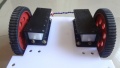
| − | ==Attaching Wheels to chasis== | + | ===Attaching Wheels to chasis=== |
[[File:RF_Robo_Attaching_wheels_2.JPG]] | [[File:RF_Robo_Attaching_wheels_2.JPG]] | ||
| − | <gallery> | + | <gallery "packed-hover"> |
File:RF_Robo_Attaching_wheels_1.JPG|Step 1 | File:RF_Robo_Attaching_wheels_1.JPG|Step 1 | ||
File:RF_Robo_Attaching_wheels_2.JPG|Step 2 | File:RF_Robo_Attaching_wheels_2.JPG|Step 2 | ||
| Line 44: | Line 71: | ||
</gallery> | </gallery> | ||
| − | ==Assembling the Base== | + | ===Assembling the Base=== |
[[File:RF_Robo_Assembly_6.JPG]] | [[File:RF_Robo_Assembly_6.JPG]] | ||
| − | <gallery> | + | <gallery "packed-hover"> |
File:RF_Robo_Assembly_1.JPG|Step 1 | File:RF_Robo_Assembly_1.JPG|Step 1 | ||
File:RF_Robo_Assembly_2.JPG|Step 2 | File:RF_Robo_Assembly_2.JPG|Step 2 | ||
| Line 52: | Line 79: | ||
File:RF_Robo_Assembly_4.JPG|Step 4 | File:RF_Robo_Assembly_4.JPG|Step 4 | ||
</gallery> | </gallery> | ||
| + | |||
| + | =Electronics= | ||
| + | ==Robo Controller Board== | ||
| + | {{Box|type=l_green_light|text=<br/> | ||
| + | *The Robo Board: This is the heart of the robot. The board has following ICs | ||
| + | **'''Motor Driver''': A L293D Motor driver on board is used to control the two driving motors of the Robot | ||
| + | **'''DTMF Decoder''': A MT8870 or compatible IC is used to convert DTMF mobile tones to digits, which helps in making Mobile controlled Robot | ||
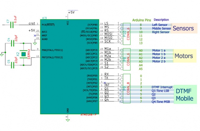
| + | **'''Microcontroller''': The board feature a Atmega8 (Atmega328 can also be used) controller. Figure below shows the way in which various units are connected to the microcontroller. | ||
| + | }} | ||
| + | [[File:Explore Robo Pinout.jpg|x430px]] | ||
| + | |||
| + | ==Sensor Sheild== | ||
| + | {{Box|type=l_green_light|text= | ||
| + | The sensor sheild has a comparator IC that gives logical high when any of the right, Middle or left sensors are detected.The sensor sheild has following sensors:<br/> | ||
| + | *3 IR pairs for line following | ||
| + | *3 IR Pairs for obstacle avoidance | ||
| + | *3 Light Dependent Resistors | ||
| + | Notice the DIP switch shown in the image below, it used to select the above three sensor options. | ||
| + | |||
| + | }} | ||
| + | [[File:Sensor sheild.jpg|x400px]] | ||
| + | |||
| + | =Downloads= | ||
| + | ==[https://github.com/ExploreEmbedded/ExploreRobo_Sample-Code/archive/master.zip Code]== | ||
| + | |||
| + | ==[http://exploreembedded.com/wiki/images/b/b4/SCHEMATIC_AVR_ROBO.pdf Robo_Board Schematic]== | ||
| + | |||
| + | ==[http://exploreembedded.com/wiki/images/b/b2/Schematic_sensor_board.pdf Sensor Sheild Schematic ]== | ||
| + | ==Bootloader: optiboot== | ||
| + | The Explore Robo uses optiboot. Find the modified source code [http://exploreembedded.com/wiki/images/1/15/Optiboot_ExploreRobo.zip here.] | ||
| + | Fuse settings on Explore Robo: | ||
| + | {| class="wikitable" | ||
| + | |- | ||
| + | ! L FUSE !! H FUSE !! LOCK | ||
| + | |- | ||
| + | | 0xFF|| 0xDC|| 0xCF | ||
| + | |} | ||
| + | |||
| + | [http://eleccelerator.com/fusecalc/fusecalc.php?chip=atmega8&LOW=FF&HIGH=DC&LOCKBIT=CF Fuse bit details] | ||
| + | '''*Do not modify fuse bits unless you're sure of what you're doing!''' | ||
| + | |||
| + | =Programming= | ||
| + | =====Using the Board with AVR Studio and Flashing with XploreFlash===== | ||
| + | {{Box|type=l_green_light|text= | ||
| + | Step 1: Xplore flash is based on various opensource software, it requires avrdude. Avrdude is part of WinAVR GCC complier. [http://sourceforge.net/projects/winavr/files/latest/download?source=files Download and install it.] | ||
| + | |||
| + | Step 2:To connect Development board with computer USB driver is required. | ||
| + | [http://xplorelabz.com/wiki/images/d/d3/CP210x_VCP_Windows.zip Windows USB to UART Drivers for CP2102] | ||
| + | *For Other Operating system please download from [http://www.silabs.com/products/mcu/pages/usbtouartbridgevcpdrivers.aspx Silicon Labs website.] | ||
| + | |||
| + | Step 3: Download and install [http://xplorelabz.com/wiki/images/e/ef/XploreFlash.zip XploreFlash GUI]. (XploreFlash GUI is based on AVRDUDESS) | ||
| + | |||
| + | Step 4: Follow the steps on images below to flash the board. | ||
| + | <gallery mode="packed-hover"> | ||
| + | File:CP2102_Device_Manager.JPG|Check for COM port | ||
| + | File:XploreFlash_Detect_MCU.JPG|Hit Detect MCU | ||
| + | File:XploreFlash_Flash_Verify.jpg|Browse file and Flash | ||
| + | </gallery> | ||
| + | |||
| + | Note: The GUI software will require [http://www.microsoft.com/en-gb/download/details.aspx?id=16614 .NET framework] 2.0 or later please download and install it. | ||
| + | }} | ||
| + | |||
| + | ===Using the Board with Arduino Software=== | ||
| + | {{Box|type=l_green_light|text=-> | ||
| + | |||
| + | For the board to appear in the arduino software add the following lines in the '''boards.txt''' file.<br/>File location:e.g: C:\Program Files\Arduino\hardware\arduino | ||
| + | }} | ||
| + | {{Box|type=l_blue_light|text= | ||
| + | #################################################<br/> | ||
| + | atmega8.name=Explore Robo w/ ATmega8<br/> | ||
| + | atmega8.upload.protocol=arduino<br/> | ||
| + | atmega8.upload.maximum_size=7168<br/> | ||
| + | atmega8.upload.speed=19200<br/> | ||
| + | atmega8.bootloader.low_fuses=0xdf<br/> | ||
| + | atmega8.bootloader.high_fuses=0xca<br/> | ||
| + | atmega8.bootloader.path=atmega8<br/> | ||
| + | atmega8.bootloader.file=ATmegaBOOT-prod-firmware-2009-11-07.hex <br/> | ||
| + | atmega8.bootloader.unlock_bits=0x3F<br/><br/> | ||
| + | atmega8.bootloader.lock_bits=0x0F<br/> | ||
| + | atmega8.build.mcu=atmega8<br/> | ||
| + | atmega8.build.f_cpu=16000000L<br/> | ||
| + | atmega8.build.core=arduino<br/> | ||
| + | atmega8.build.variant=standard<br/> | ||
| + | }} | ||
| + | |||
| + | ====Steps==== | ||
| + | <gallery mode="packed-hover"> | ||
| + | File:Detect Board.png|1.The board shows up in arduino software | ||
| + | File:CP2102 Device Manager.JPG|2.Check exact COM port | ||
| + | File:Select_COM.png|3.Select the COM port. | ||
| + | </gallery> | ||
| + | |||
| + | ====Arduino Examples==== | ||
| + | *[[Computer controlled Robot with Arduino]] | ||
| + | *[[Mobile controlled Robot with Arduino]] | ||
| + | |||
| + | {{DISQUS}} | ||
Latest revision as of 18:19, 10 September 2015


.JPG)
.JPG)
.JPG)
.JPG)
- Robotics board based on Atmega8 MCU.
- Sensor shield to make line follower, light follower and obstacle avoidance robot.
- Inbuilt DTMF decoder (MT8870) to make a Mobile controlled Robot
- USB to UART convertor (CP2102) for communicating with computer, make a computer controlled Robot.
- MCU with bootloader, no external programmer required.
- Compatible with Arduino Software.
- Electronics
- Robotics Board Based on Atmega8, with L293D driver and MT8870 DTMF Decoder
- Sensor Sheild for line, light and obstacle detecting robots
- Mechanical
- Chasis(Red and White Basis)
- BO Motor Clamps
- DC BO Motors 150 RPM
- Wheels x2
- Castor Wheel
- Screws
- Battery Holder x2
- Other
- USB Cable
- 5 Pin Sensor cable
Mechanical
Assembling the Robot
Quick Video
Mounting the BO Motor with Clamps

Step 1
Step 2
Step 3
Step 4

Step 5
Step 6
Attaching Wheels to chasis
Step 1
Step 2
Step 3
Step 4
Assembling the Base
Step 1
Step 2
Step 3
Step 4
Electronics
Robo Controller Board
- The Robo Board: This is the heart of the robot. The board has following ICs
- Motor Driver: A L293D Motor driver on board is used to control the two driving motors of the Robot
- DTMF Decoder: A MT8870 or compatible IC is used to convert DTMF mobile tones to digits, which helps in making Mobile controlled Robot
- Microcontroller: The board feature a Atmega8 (Atmega328 can also be used) controller. Figure below shows the way in which various units are connected to the microcontroller.
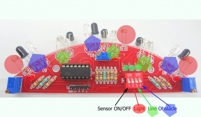
Sensor Sheild
The sensor sheild has a comparator IC that gives logical high when any of the right, Middle or left sensors are detected.The sensor sheild has following sensors:
- 3 IR pairs for line following
- 3 IR Pairs for obstacle avoidance
- 3 Light Dependent Resistors
Notice the DIP switch shown in the image below, it used to select the above three sensor options.
Downloads
Code
Robo_Board Schematic
Sensor Sheild Schematic
Bootloader: optiboot
The Explore Robo uses optiboot. Find the modified source code here. Fuse settings on Explore Robo:
L FUSE H FUSE LOCK 0xFF 0xDC 0xCF Fuse bit details *Do not modify fuse bits unless you're sure of what you're doing!
Programming
Using the Board with AVR Studio and Flashing with XploreFlash
Step 1: Xplore flash is based on various opensource software, it requires avrdude. Avrdude is part of WinAVR GCC complier. Download and install it.Step 2:To connect Development board with computer USB driver is required. Windows USB to UART Drivers for CP2102
- For Other Operating system please download from Silicon Labs website.
Step 3: Download and install XploreFlash GUI. (XploreFlash GUI is based on AVRDUDESS)
Step 4: Follow the steps on images below to flash the board.
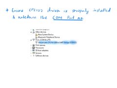
Check for COM port
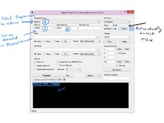
Hit Detect MCU
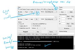
Browse file and Flash
Note: The GUI software will require .NET framework 2.0 or later please download and install it.
Using the Board with Arduino Software
->For the board to appear in the arduino software add the following lines in the boards.txt file.
File location:e.g: C:\Program Files\Arduino\hardware\arduino#################################################
atmega8.name=Explore Robo w/ ATmega8
atmega8.upload.protocol=arduino
atmega8.upload.maximum_size=7168
atmega8.upload.speed=19200
atmega8.bootloader.low_fuses=0xdf
atmega8.bootloader.high_fuses=0xca
atmega8.bootloader.path=atmega8
atmega8.bootloader.file=ATmegaBOOT-prod-firmware-2009-11-07.hex
atmega8.bootloader.unlock_bits=0x3F
atmega8.bootloader.lock_bits=0x0F
atmega8.build.mcu=atmega8
atmega8.build.f_cpu=16000000L
atmega8.build.core=arduino
atmega8.build.variant=standard
Steps
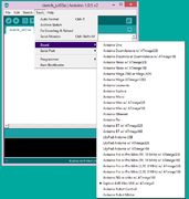
1.The board shows up in arduino software
2.Check exact COM port
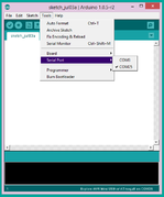
3.Select the COM port.
Arduino Examples


