
Difference between revisions of "Explore POV"
| (27 intermediate revisions by 2 users not shown) | |||
| Line 1: | Line 1: | ||
[[category: DIY Hobby Kits]] | [[category: DIY Hobby Kits]] | ||
| + | [[User:Sandeep|Sandeep]] ([[User talk:Sandeep|talk]]) 15:35, 6 March 2015 (IST) | ||
| + | ---- | ||
| − | [[File:POV poster copy.jpg | + | The colorful Persistence Of Vision (POV) kit enables you to create colorful messages in air with just 8 LEDs. This kit is great introduction to soldering and AVR/Arduino Programming. The kit does not require a external programmer, it is self programmable with USB. |
| + | |||
| + | |||
| + | [[File:POV poster copy.jpg]] | ||
<gallery mode="packed-hover"> | <gallery mode="packed-hover"> | ||
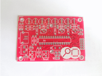
File:Explore POV final.jpg|DIY Kit contains | File:Explore POV final.jpg|DIY Kit contains | ||
| Line 7: | Line 12: | ||
</gallery> | </gallery> | ||
| − | + | ||
=Solder it!= | =Solder it!= | ||
| − | *Image | + | [[File:POV_Board_Soldering_Steps.gif|framed|POV Sequence for Soldering the Board]] |
| + | *Image above shows the layout of various components for the board. It is also printed on the PCB. | ||
| + | *The image sequence shows, how to mount and solder components! | ||
==Component Layout== | ==Component Layout== | ||
The image shows reference numbers for all the components. | The image shows reference numbers for all the components. | ||
| Line 162: | Line 169: | ||
| | | | ||
| − | <center> | + | <center>22</center> |
| | | | ||
| Line 208: | Line 215: | ||
|} | |} | ||
| + | |||
=Programming= | =Programming= | ||
| + | ==C Code== | ||
| + | <syntaxhighlight> | ||
| + | #include <avr/io.h> | ||
| + | #include<util/delay.h> | ||
| + | #include<stdint.h> | ||
| + | #include<avr/interrupt.h> | ||
| + | |||
| + | #define Blue 3 | ||
| + | #define Green 4 | ||
| + | #define Red 5 | ||
| + | |||
| + | uint8_t i=0; | ||
| + | |||
| + | |||
| + | const static uint16_t image[]= | ||
| + | { | ||
| + | 0b0000100011111111, 0b0000100011111111, 0b0000100011111111, 0b0000100011111111, | ||
| + | 0b0000100011111111, 0b0000100011111111, 0b0000100011111111, 0b0000000000000000, | ||
| + | 0b0000010011111110, 0b0000010000010001, 0b0000010000010001, 0b0000010000010001, | ||
| + | 0b0000010011100001, 0b0000000000000000, 0b0000010001111110, 0b0000010010010001, | ||
| + | 0b0000010010010001, 0b0000010010010001, 0b0000010000001110, 0b0000000000000000, | ||
| + | 0b0000001011111111, 0b0000001000010001, 0b0000001000010001, 0b0000001000010001, | ||
| + | 0b0000001000001110, 0b0000000000000000, 0b0000001000001110, 0b0000001000010001, | ||
| + | 0b0000001000010001, 0b0000001011111111, 0b0000000000000000, 0b0000000000000000, | ||
| + | 0b0000100001110000, 0b0000100011111100, 0b0000100011111110, 0b0000100011111111, | ||
| + | 0b0000100011111111, 0b0000100011111110, 0b0000100011111100, 0b0000100001111000, | ||
| + | 0b0000000000000000, 0b0000000000000000, 0b0000010011111110, 0b0000010000010001, | ||
| + | 0b0000010000010001, 0b0000010000010001, 0b0000010011100001, 0b0000000000000000, | ||
| + | 0b0000001001110000, 0b0000001010001000, 0b0000001010001000, 0b0000001010001000, | ||
| + | 0b0000001011111111, 0b0000000000000000, 0b0000001001110000, 0b0000001010001000, | ||
| + | 0b0000001010001000, 0b0000001010001000, 0b0000001011111111, 0b0000000000000000, | ||
| + | 0b0000010001111110, 0b0000010010010001, 0b0000010010010001, 0b0000010010010001, | ||
| + | 0b0000010010001111, 0b0000000000000000, 0b0000000000000000, 0b0000010011111111, | ||
| + | 0b0000010000010000, 0b0000010000010000, 0b0000010000010000, 0b0000010011111111 | ||
| + | }; | ||
| + | |||
| + | void disp(uint16_t); | ||
| + | |||
| + | ISR (TIMER1_OVF_vect) // Timer1 ISR | ||
| + | { | ||
| + | disp(image[i]); | ||
| + | i++; | ||
| + | |||
| + | if(i==72) | ||
| + | i=0; | ||
| + | |||
| + | TCNT1H=0xFF; // Reload the 16-bit count value | ||
| + | TCNT1L=0xF0; // in timer1 count registers | ||
| + | } | ||
| + | |||
| + | |||
| + | int main(void) | ||
| + | { | ||
| + | DDRC = 0b11111111; | ||
| + | DDRD = 0b11111111; | ||
| + | |||
| + | PORTC = 0b11111111; | ||
| + | PORTD = 0b00000111; | ||
| + | |||
| + | TCNT1H=0xFF; // Load the 16-bit count value | ||
| + | TCNT1L=0xF0; // for 1 sec at 7.3728MHz | ||
| + | |||
| + | TCCR1A=0x00; | ||
| + | TCCR1B=0x05; // Timer mode with 1024 prescAler | ||
| + | TIMSK=0x04; // Enable timer1 overflow interrupt(TOIE1) | ||
| + | sei(); // Enable global interrupts by setting global interrupt enable bit in SREG | ||
| + | |||
| + | while(1) | ||
| + | { | ||
| + | |||
| + | } | ||
| + | } | ||
| + | |||
| + | void disp(uint16_t pat) | ||
| + | { | ||
| + | |||
| + | PORTC = pat & 0x3f; | ||
| + | PORTD = (pat>>6)& 0xff; | ||
| + | } | ||
| + | |||
| + | |||
| + | </syntaxhighlight> | ||
| + | |||
| + | ==Arduino Code== | ||
| + | Arduino Code will be uploaded soon. | ||
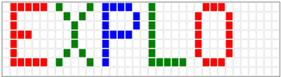
==Pattern Generation== | ==Pattern Generation== | ||
| − | To create an image/ | + | To create an image/patterm, you can use the POV image maker application. |
| − | [[ | + | [[Image:Maker.PNG|400px|link=http://pov.exploreembedded.com/ImageMaker.html]] |
==Uploading the Pattern== | ==Uploading the Pattern== | ||
| + | * [http://www.fischl.de/usbasp/usbasp-windriver.2011-05-28.zip Install USBasp driver] on your computer. Note that the it will show up as not recognized if the reset sequence is not followed | ||
| + | ===Reset Sequence for uploading new pattern/image=== | ||
| + | [[File:Pov-reset.gif|framed|right|POV Reset Sequence for uploading new image]] | ||
| + | *Perform reset sequence every time you connect the kit to the computer. | ||
| + | * To upload a new image, '''hold down the BOOT button, press and release the RESET button and then release the BOOT button''' as shown below. | ||
| + | * Note the LEDS will stop blinking once the kit is detected by the computer. | ||
| + | |||
| + | =Downloads= | ||
| + | *[http://exploreembedded.com/wiki/images/b/b3/Explore_POV_v1.pdf Schematic] | ||
| + | {{DISQUS}} | ||
Latest revision as of 15:32, 17 May 2016
Sandeep (talk) 15:35, 6 March 2015 (IST)
The colorful Persistence Of Vision (POV) kit enables you to create colorful messages in air with just 8 LEDs. This kit is great introduction to soldering and AVR/Arduino Programming. The kit does not require a external programmer, it is self programmable with USB.

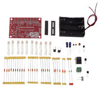
DIY Kit contains
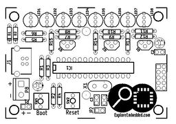
Component Placement
Contents
Solder it!
 POV Sequence for Soldering the Board
- Image above shows the layout of various components for the board. It is also printed on the PCB.
- The image sequence shows, how to mount and solder components!
Component Layout
The image shows reference numbers for all the components.
- From the table below find out the exact part for the reference number.
Component List
ref value Item count C1 4.7uF 1 C2 100nF 1 C3,C4 22pF 2 CON1 AVR-ISP-10 1 D1,D2 3.6V Zener 2 IC1 ATMEGA8-P 1 J1 USB_2 1 LED1..LED8 LED-RGB 8 P8 Batt 1 Q1..Q3 BC547 3 R1 2.2K 1 R2,R3 68E 2 R4 10K 1 R5..R12 22 8 R13..R15 1K 3 SW1 Boot 1 SW2 Reset 1 X1 12MHz 1 Programming
C Code
#include <avr/io.h>
#include<util/delay.h>
#include<stdint.h>
#include<avr/interrupt.h>

#define Blue 3
#define Green 4
#define Red 5

uint8_t i=0;


const static uint16_t image[]=
{
0b0000100011111111, 0b0000100011111111, 0b0000100011111111, 0b0000100011111111,
0b0000100011111111, 0b0000100011111111, 0b0000100011111111, 0b0000000000000000,
0b0000010011111110, 0b0000010000010001, 0b0000010000010001, 0b0000010000010001,
0b0000010011100001, 0b0000000000000000, 0b0000010001111110, 0b0000010010010001,
0b0000010010010001, 0b0000010010010001, 0b0000010000001110, 0b0000000000000000,
0b0000001011111111, 0b0000001000010001, 0b0000001000010001, 0b0000001000010001,
0b0000001000001110, 0b0000000000000000, 0b0000001000001110, 0b0000001000010001,
0b0000001000010001, 0b0000001011111111, 0b0000000000000000, 0b0000000000000000,
0b0000100001110000, 0b0000100011111100, 0b0000100011111110, 0b0000100011111111,
0b0000100011111111, 0b0000100011111110, 0b0000100011111100, 0b0000100001111000,
0b0000000000000000, 0b0000000000000000, 0b0000010011111110, 0b0000010000010001,
0b0000010000010001, 0b0000010000010001, 0b0000010011100001, 0b0000000000000000,
0b0000001001110000, 0b0000001010001000, 0b0000001010001000, 0b0000001010001000,
0b0000001011111111, 0b0000000000000000, 0b0000001001110000, 0b0000001010001000,
0b0000001010001000, 0b0000001010001000, 0b0000001011111111, 0b0000000000000000,
0b0000010001111110, 0b0000010010010001, 0b0000010010010001, 0b0000010010010001,
0b0000010010001111, 0b0000000000000000, 0b0000000000000000, 0b0000010011111111,
0b0000010000010000, 0b0000010000010000, 0b0000010000010000, 0b0000010011111111
};

void disp(uint16_t);

ISR (TIMER1_OVF_vect)    // Timer1 ISR
{
	disp(image[i]);
	i++;

	if(i==72)
	i=0;

	TCNT1H=0xFF;    // Reload the 16-bit count value
	TCNT1L=0xF0;    // in timer1 count registers
}


int main(void)
{
    DDRC = 0b11111111;
	DDRD = 0b11111111;

	PORTC = 0b11111111;
	PORTD = 0b00000111;

	TCNT1H=0xFF;   // Load the 16-bit count value
	TCNT1L=0xF0;   // for 1 sec at 7.3728MHz

	TCCR1A=0x00;
	TCCR1B=0x05;  // Timer mode with 1024 prescAler
	TIMSK=0x04;   // Enable timer1 overflow interrupt(TOIE1)
	sei();        // Enable global interrupts by setting global interrupt enable bit in SREG

    while(1)
    {

    }
}

void disp(uint16_t pat)
{

	PORTC = pat & 0x3f;
	PORTD = (pat>>6)& 0xff;
}
Arduino Code
Arduino Code will be uploaded soon.
Pattern Generation
To create an image/patterm, you can use the POV image maker application.
Uploading the Pattern
- Install USBasp driver on your computer. Note that the it will show up as not recognized if the reset sequence is not followed
Reset Sequence for uploading new pattern/image
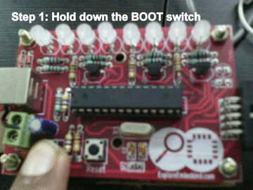 POV Reset Sequence for uploading new image
- Perform reset sequence every time you connect the kit to the computer.
- To upload a new image, hold down the BOOT button, press and release the RESET button and then release the BOOT button as shown below.
- Note the LEDS will stop blinking once the kit is detected by the computer.
Downloads


