|
|
| Line 1: |
Line 1: |
| | [[Category:PIC Tutorials]] | | [[Category:PIC Tutorials]] |
| | | | |
| − | The Explore Ultra PIC Kit comes with all the things required, not just for this experiment but for the entire series. And even if you think of migrating to PIC or Arduino, you'll have breakout boards that fit on to this, hence we believe it is a great investment for learning hands on Embedded Systems. The kit is fully open source, you may use the schematics, the design files and all of the source code and build something cool on your own. And when you do that do not forget to share with us what you've done. We would be happy to see you building something cool.
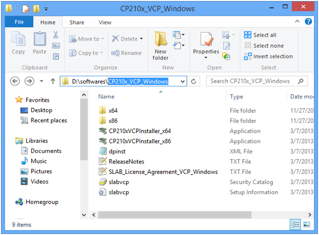
| + | Follow the below steps to install the Usb-To-Serial drivers. |
| | | | |
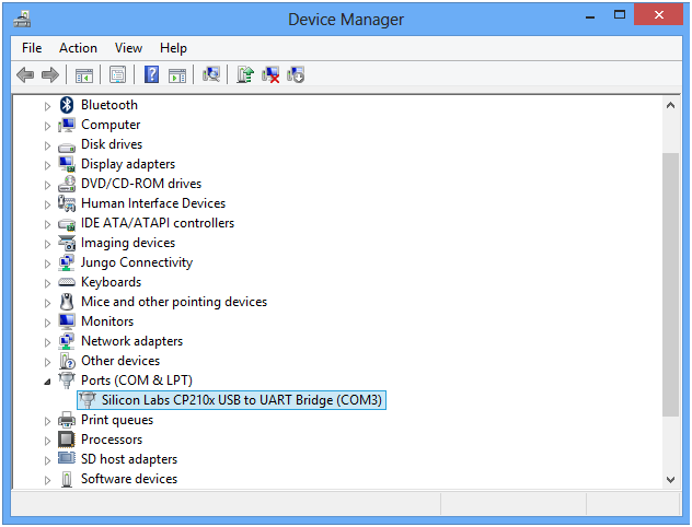
| − | [[FILE:Ultra one.PNG]] | + | Step1: Connect the USB2Serial breakout/Starter 8051 board to system using the USB cable. |
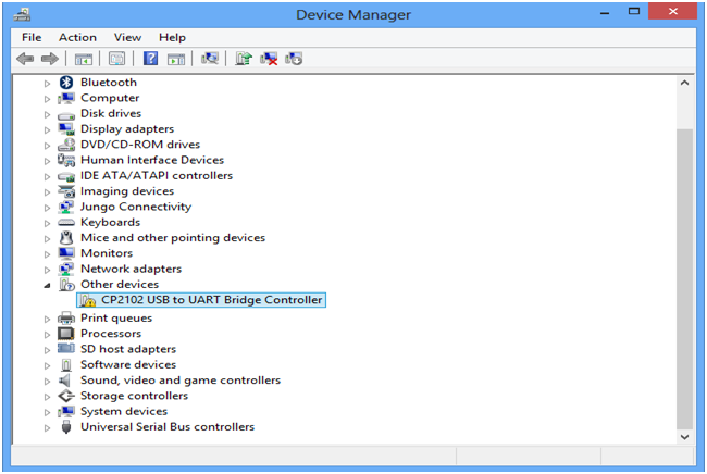
| | + | Open the device manager, now the device will be listed in other devices as proper drivers are not installed. |
| | + | [[FILE:Usb2Serial 01.png]] |
| | | | |
| − | The latest version of Ultra PIC dev kit is modular in both hardware and software. The kit comprises of the Ultra One Base Board and PIC breakout board as the main components.
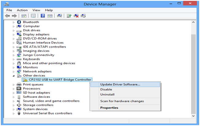
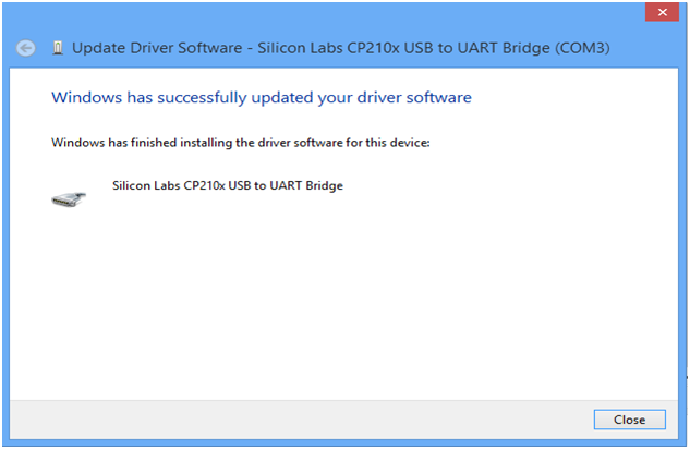
| + | Step2: Now right click on the Cp2102 Usb to UART Bridge Controller and select Update Driver Software option. |
| | + | [[FILE:Usb2Serial 02.png]] |
| | | | |
| − | The PIC breakout board comes with 16F877A, however you may use any other 40 pin PIC MCUs like the 18F4550. The 16F877A comes with a UART bootloader hence no external programmer is required.
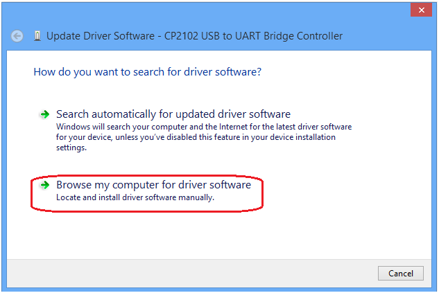
| + | Step2: Now right click on the Cp2102 Usb to UART Bridge Controller and select Update Driver Software option. |
| | + | [[FILE:Usb2Serial 03.png]] |
| | | | |
| − | The Ultra One baseboard can additionally be used with several AVR, 8051 and Arduino Microcontrollers, we beleive this kit to is a solid gate way to Embedded Systems. This is not it, even the USB to Serial Convertor on board is moduler, you can take it off and use it any of the other projects. The base board is fully open, no peripheral is directly connected to the MCU breakout board. You may connect any peripheral to any port/pin you wish.
| + | Step2: Now right click on the Cp2102 Usb to UART Bridge Controller and select Update Driver Software option. |
| | + | [[FILE:Usb2Serial 04.png]] |
| | | | |
| − | The newer version also supports 128x64 Graphics display as well as 128x64 OLED display. The story of the Ultra Kit does not end here, we have even made the code libraries for all major 8 bit microcontrollers modular. It means you can simple upgrade or even switch your project to a different microcontroller/architecture without changing your application code. The kit ships with all the additional stuff mentioned below to get you started; kickstart you're embedded development. What are you waiting for?
| + | Step2: Now right click on the Cp2102 Usb to UART Bridge Controller and select Update Driver Software option. |
| | + | [[FILE:Usb2Serial 05.png]] |
| | | | |
| − | Kit Contents:
| + | Step2: Now right click on the Cp2102 Usb to UART Bridge Controller and select Update Driver Software option. |
| − | Explore ULTRA PIC Development Board with following Modules, ICs and Interfaces:
| + | [[FILE:Usb2Serial 06.png]] |
| − | #DS1307 RTC.
| + | |
| − | #24C16 EEPROM
| + | |
| − | #Micro SD
| + | |
| − | #Four Seven Segment Displays
| + | |
| − | #Eight LEDs
| + | |
| − | #4 x 4 Keypad
| + | |
| − | #Temperature Sensor LM35
| + | |
| − | #LDR
| + | |
| − | #Buzzer
| + | |
| − | #L293D Motor Driver.
| + | |
| − | #Two Relays.
| + | |
| − | #Eight DIP switches.
| + | |
| − | #Breakout for 20X4 character LCD.
| + | |
| − | #Breakout for 128X64 LCD.
| + | |
| − | #Breakout for OLED.
| + | |
| − | #Breakout for Zigbee.
| + | |
| − | | + | |
| − | =Driver Installation=
| + | |
| − | *Usb2Serial Driver Installation.
| + | |
| − | | + | |
| − | =Software Setup=
| + | |
| − | *Compiler Installation: Download and Install the MPlabx IDE and x8 compiler.
| + | |
| − | *Check [[PIC Software Setup|this tutorial]] for setting up the project to generate the .hex file.
| + | |
| − | * [[Flashing Hex File Using Pickit2|Uploading Hex File Using Pickit2.]]
| + | |
| − | * [[Uploading Hex File Using Ds30 Bootloader|Uploading Hex File Using Ds30 Bootloader.]]
| + | |
| − | | + | |
| − | =Complete Board Test=
| + | |
| − | The board is shipped with test software loaded in the controller, follow the below procedure to test all the peripherals.
| + | |
| − | | + | |
| − | ===GPIO Test===
| + | |
| − | | + | |
| − | ===LCD 8-bit Test===
| + | |
| − | | + | |
| − | ===LCD 4-bit Test===
| + | |
| − | | + | |
| − | ===Seven Segment Test===
| + | |
| − | | + | |
| − | ===RTC Test===
| + | |
| − | | + | |
| − | ===EEprom Test===
| + | |
| − | | + | |
| − | ===Adc Test===
| + | |
| − | | + | |
| − | ===Keypad Test===
| + | |
Step1: Connect the USB2Serial breakout/Starter 8051 board to system using the USB cable.
Open the device manager, now the device will be listed in other devices as proper drivers are not installed.
Step2: Now right click on the Cp2102 Usb to UART Bridge Controller and select Update Driver Software option.
Step2: Now right click on the Cp2102 Usb to UART Bridge Controller and select Update Driver Software option.
Step2: Now right click on the Cp2102 Usb to UART Bridge Controller and select Update Driver Software option.
Step2: Now right click on the Cp2102 Usb to UART Bridge Controller and select Update Driver Software option.
Step2: Now right click on the Cp2102 Usb to UART Bridge Controller and select Update Driver Software option.