Difference between revisions of "ALU in Detail"
| Line 58: | Line 58: | ||
}} | }} | ||
| − | [[File:1bitALU.jpg| | + | [[File:1bitALU.jpg|1000x480px|1 bit ALU]] |
{| class="wikitable" style="text-align:left" | {| class="wikitable" style="text-align:left" | ||
Revision as of 13:21, 8 December 2013
Arithmetic and Logic Unit in Detail
You should have heard of an Arithmetic and Logic Unit before, while discussing a Computer CPU or a micro controller. In this tutorial we will look at what an ALU really is?
We will discuss a 4 bit ALU; this would limit many possibilities 16. We would assume that associated registers and instruction set are also 4 bit.
We will discuss a 4 bit ALU; this would limit many possibilities 16. We would assume that associated registers and instruction set are also 4 bit.
Half Adder
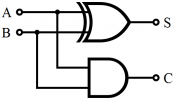
half adder adds two single binary digits A and B. It has two outputs, sum (S) and carry (C). The carry signal represents an overflow into the next digit of a multi-digit addition.Figures below illustrate a simple half adder constructed from logic gates
| Inputs | Outputs | ||
|---|---|---|---|
| A | B | S | C |
| 0 | 0 | 0 | 0 |
| 1 | 0 | 1 | 0 |
| 0 | 1 | 1 | 0 |
| 1 | 1 | 0 | 1 |
Full Adder
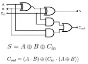
Full Adder is an extension of half adder to include the Cin input as well. The truth table can be implemented to form the logic diagram as shown below.
| Inputs | Outputs | |||
|---|---|---|---|---|
| A | B | Cin | Cout | S |
| 0 | 0 | 0 | 0 | 0 |
| 1 | 0 | 0 | 0 | 1 |
| 0 | 1 | 0 | 0 | 1 |
| 1 | 1 | 0 | 1 | 0 |
| 0 | 0 | 1 | 0 | 1 |
| 1 | 0 | 1 | 1 | 0 |
| 0 | 1 | 1 | 1 | 0 |
| 1 | 1 | 1 | 1 | 1 |
The basic Unit: 1 bit ALU
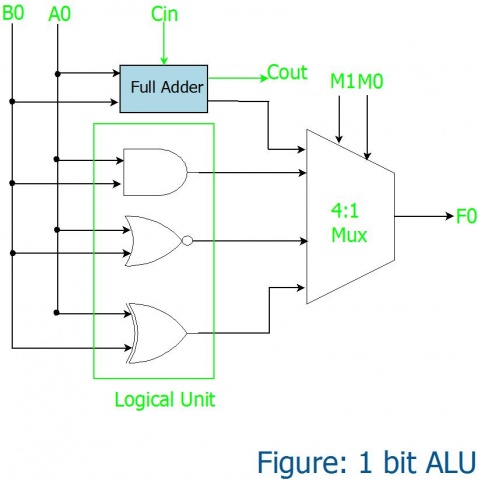
So with the above building blocks, lets construct a simple ALU that performs a arithmetic operation (1 bit addition)and does 3 logical operations namely AND, NOR and XOR as shown below. The multiplexer selects only one operation at a time.
The operation selected depends on the selection lines of the multiplexer as shown in the truth table.
| Inputs | Outputs | ||
|---|---|---|---|
| M1 | M0 | Operation | |
| 0 | 0 | SUM | |
| 1 | 0 | AND | |
| 0 | 1 | OR | |
| 1 | 1 | XOR | |


