|
|
| (59 intermediate revisions by 5 users not shown) |
| Line 1: |
Line 1: |
| − | {{Box|type=l_green_light|text=<br />
| + | [[Category:8051_tutorials]] |
| − | =Introduction:LCD=
| + | In this tutorial we are going to see how to interface a 2x16 LCD with 8051 in 8-bit mode. |
| | + | As per the name the 2x16 has 2 lines with 16 chars on each lines. It supports all the ascii chars and is basically used for displaying the alpha numeric characters. Here each character is displayed in a matrix of 5x7 pixels. |
| | + | Apart from alpha numeric chars it also provides the provision to display the custom characters by creating the pattern. |
| | | | |
| − | Liquid Crystal Display(LCDs) provide a cost effective way to put a text output unit for a microcontroller. As we have seen in the previous tutorial, LEDs or 7 Segments do no have the flexibility to display informative messages.
| |
| − | This display has 2 lines and can display 16 characters on each line. Nonetheless, when it is interfaced with the micrcontroller, we can scroll the messages with software to display information which is more than 16 characters in length.
| |
| − |
| |
| − | == LCD Internal Controller==
| |
| − | [[File:HD44780U Block diagram.png|570x250px|framed|Fig 1: LCD Block diagram]]<br />
| |
| − |
| |
| − | The LCD is a simple device to use but the internal details are complex. Most of the 16x2 LCDs use a '''Hitachi HD44780''' or a compatible controller. Yes, a micrcontroller is present inside a Liquid crystal display as shown in figure 1.
| |
| − | [[File:LCD Char 5x7 Matrix.jpg|thumbnail]]
| |
| − | The Display Controller takes commands and data from a external microcontroller and drivers the LCD panel'''(LCDP)'''.
| |
| − | It takes a ASCII value as input and generate a patter for the dot matrix. E.g., to display letter 'A', it takes its value '''0X42(hex)''' or '''66(dec)''' decodes it into a dot matrix of 5x7 as shown in figure 2.
| |
| − |
| |
| − | ==Basic Commands==
| |
| − | The LCD controller uses RS and RW lines along with E to operate the LCD.
| |
| − | *'''Resister Select (RS)''': Determines weather a command(RS = 0) is sent (to set up the display) or actual data(RS=1) is sent.
| |
| − | *'''Read/Write''' RW=0; writes to the LCD. RW=1;Reads from the LCD.
| |
| − | The commonly used instructions are shown in the instruction set below.
| |
| − | Observe the '''Bit names: I/D, S, D, C''' etc at the bottom of instruction set to decode the instructions completely.
| |
| − | *Clear Display
| |
| − | *Cursor Home
| |
| − | *Set Entry Mode
| |
| − | *Display on/off control
| |
| − | *Cursor/display shift
| |
| − | *Function Set
| |
| − | *Read Busy Flag
| |
| − | *Data Read
| |
| − | *Data Write<br />
| |
| − |
| |
| − | }}
| |
| − | ==Instruction Set==
| |
| − | {|class="wikitable" border="1" cellpadding="10" cellspacing="0" align="center"
| |
| − |
| |
| − | |+ '''HD44780U based instruction set'''
| |
| − |
| |
| − | |-
| |
| − |
| |
| − | ! style="background: #efefef;" rowspan="2" | Instruction
| |
| − |
| |
| − | ! style="background: #efefef;" colspan="10" | Code
| |
| − |
| |
| − | ! style="background: #efefef;" rowspan="2" | Description
| |
| − |
| |
| − | |-
| |
| − |
| |
| − | ! style="background: #efefef; border-right: 0px;" | RS
| |
| − |
| |
| − | ! style="background: #efefef; border-right: 0px; border-left: 0px;" | R/W
| |
| − |
| |
| − | ! style="background: #efefef; border-right: 0px; border-left: 1px dashed;" | B7
| |
| − |
| |
| − | ! style="background: #efefef; border-right: 0px; border-left: 0px;" | B6
| |
| − |
| |
| − | ! style="background: #efefef; border-right: 0px; border-left: 0px;" | B5
| |
| − |
| |
| − | ! style="background: #efefef; border-right: 0px; border-left: 0px;" | B4
| |
| − |
| |
| − | ! style="background: #efefef; border-right: 0px; border-left: 0px;" | B3
| |
| − |
| |
| − | ! style="background: #efefef; border-right: 0px; border-left: 0px;" | B2
| |
| − |
| |
| − | ! style="background: #efefef; border-right: 0px; border-left: 0px;" | B1
| |
| − |
| |
| − | ! style="background: #efefef; border-left: 0px;" | B0
| |
| − |
| |
| − | |-
| |
| − |
| |
| − | | Clear display
| |
| − |
| |
| − | |align="center" style="border-right: 0px;"| 0
| |
| − |
| |
| − | |align="center" style="border-right: 0px; border-left: 0px;"| 0
| |
| − |
| |
| − | |align="center" style="border-right: 0px; border-left: 1px dashed;"| 0
| |
| − |
| |
| − | |align="center" style="border-right: 0px; border-left: 0px;"| 0
| |
| − |
| |
| − | |align="center" style="border-right: 0px; border-left: 0px;"| 0
| |
| − |
| |
| − | |align="center" style="border-right: 0px; border-left: 0px;"| 0
| |
| − |
| |
| − | |align="center" style="border-right: 0px; border-left: 0px;"| 0
| |
| − |
| |
| − | |align="center" style="border-right: 0px; border-left: 0px;"| 0
| |
| − |
| |
| − | |align="center" style="border-right: 0px; border-left: 0px;"| 0
| |
| − |
| |
| − | |align="center" style="border-left: 0px;"| 1
| |
| − |
| |
| − | || Clears display and returns cursor to the home position (address 0).
| |
| − |
| |
| − | |-
| |
| − |
| |
| − | || Cursor home
| |
| − |
| |
| − | |align="center" style="border-right: 0px;"| 0
| |
| − |
| |
| − | |align="center" style="border-right: 0px; border-left: 0px;"| 0
| |
| − |
| |
| − | |align="center" style="border-right: 0px; border-left: 1px dashed;"| 0
| |
| − |
| |
| − | |align="center" style="border-right: 0px; border-left: 0px;"| 0
| |
| − |
| |
| − | |align="center" style="border-right: 0px; border-left: 0px;"| 0
| |
| − |
| |
| − | |align="center" style="border-right: 0px; border-left: 0px;"| 0
| |
| − |
| |
| − | |align="center" style="border-right: 0px; border-left: 0px;"| 0
| |
| − |
| |
| − | |align="center" style="border-right: 0px; border-left: 0px;"| 0
| |
| − |
| |
| − | |align="center" style="border-right: 0px; border-left: 0px;"| 1
| |
| − |
| |
| − | |align="center" style="border-left: 0px;"| *
| |
| − |
| |
| − | || Returns cursor to home position. Also returns display being shifted to the original position. DDRAM content remains unchanged.
| |
| − |
| |
| − |
| |
| − | |-
| |
| − |
| |
| − | || Entry mode set
| |
| − |
| |
| − | |align="center" style="border-right: 0px;"| 0
| |
| − |
| |
| − | |align="center" style="border-right: 0px; border-left: 0px;"| 0
| |
| − |
| |
| − | |align="center" style="border-right: 0px; border-left: 1px dashed;"| 0
| |
| − |
| |
| − | |align="center" style="border-right: 0px; border-left: 0px;"| 0
| |
| − |
| |
| − | |align="center" style="border-right: 0px; border-left: 0px;"| 0
| |
| − |
| |
| − | |align="center" style="border-right: 0px; border-left: 0px;"| 0
| |
| − |
| |
| − | |align="center" style="border-right: 0px; border-left: 0px;"| 0
| |
| − |
| |
| − | |align="center" style="border-right: 0px; border-left: 0px;"| 1
| |
| − |
| |
| − | |align="center" style="border-right: 0px; border-left: 0px;"| I/D
| |
| − |
| |
| − | |align="center" style="border-left: 0px;"| S
| |
| − |
| |
| − | || Sets cursor move direction (I/D); specifies to shift the display (S). These operations are performed during data read/write.
| |
| − |
| |
| − |
| |
| − | |-
| |
| − |
| |
| − | || Display on/off control
| |
| − |
| |
| − | |align="center" style="border-right: 0px;"| 0
| |
| − |
| |
| − | |align="center" style="border-right: 0px; border-left: 0px;"| 0
| |
| − |
| |
| − | |align="center" style="border-right: 0px; border-left: 1px dashed;"| 0
| |
| − |
| |
| − | |align="center" style="border-right: 0px; border-left: 0px;"| 0
| |
| − |
| |
| − | |align="center" style="border-right: 0px; border-left: 0px;"| 0
| |
| − |
| |
| − | |align="center" style="border-right: 0px; border-left: 0px;"| 0
| |
| − |
| |
| − | |align="center" style="border-right: 0px; border-left: 0px;"| 1
| |
| − |
| |
| − | |align="center" style="border-right: 0px; border-left: 0px;"| D
| |
| − |
| |
| − | |align="center" style="border-right: 0px; border-left: 0px;"| C
| |
| − |
| |
| − | |align="center" style="border-left: 0px;"| B
| |
| − |
| |
| − | || Sets on/off of all display (D), cursor on/off (C), and blink of cursor position character (B).
| |
| − |
| |
| − |
| |
| − | |-
| |
| − |
| |
| − | || Cursor/display shift
| |
| − |
| |
| − | |align="center" style="border-right: 0px;"| 0
| |
| − |
| |
| − | |align="center" style="border-right: 0px; border-left: 0px;"| 0
| |
| − |
| |
| − | |align="center" style="border-right: 0px; border-left: 1px dashed;"| 0
| |
| − |
| |
| − | |align="center" style="border-right: 0px; border-left: 0px;"| 0
| |
| − |
| |
| − | |align="center" style="border-right: 0px; border-left: 0px;"| 0
| |
| − |
| |
| − | |align="center" style="border-right: 0px; border-left: 0px;"| 1
| |
| − |
| |
| − | |align="center" style="border-right: 0px; border-left: 0px;"| S/C
| |
| − |
| |
| − | |align="center" style="border-right: 0px; border-left: 0px;"| R/L
| |
| − |
| |
| − | |align="center" style="border-right: 0px; border-left: 0px;"| *
| |
| − |
| |
| − | |align="center" style="border-left: 0px;"| *
| |
| − |
| |
| − | || Sets cursor-move or display-shift (S/C), shift direction (R/L). DDRAM content remains unchanged.
| |
| − |
| |
| − |
| |
| − | |-
| |
| − |
| |
| − | || Function set
| |
| − |
| |
| − | |align="center" style="border-right: 0px;"| 0
| |
| − |
| |
| − | |align="center" style="border-right: 0px; border-left: 0px;"| 0
| |
| − |
| |
| − | |align="center" style="border-right: 0px; border-left: 1px dashed;"| 0
| |
| − |
| |
| − | |align="center" style="border-right: 0px; border-left: 0px;"| 0
| |
| − |
| |
| − | |align="center" style="border-right: 0px; border-left: 0px;"| 1
| |
| − |
| |
| − | |align="center" style="border-right: 0px; border-left: 0px;"| DL
| |
| − |
| |
| − | |align="center" style="border-right: 0px; border-left: 0px;"| N
| |
| − |
| |
| − | |align="center" style="border-right: 0px; border-left: 0px;"| F
| |
| − |
| |
| − | |align="center" style="border-right: 0px; border-left: 0px;"| *
| |
| − |
| |
| − | |align="center" style="border-left: 0px;"| *
| |
| − |
| |
| − | || Sets interface data length (DL), number of display line (N), and character font (F).
| |
| − |
| |
| − | |-
| |
| − |
| |
| − | || Read busy flag &<br> address counter
| |
| − |
| |
| − | |align="center" style="border-right: 0px;"| 0
| |
| − |
| |
| − | |align="center" style="border-right: 0px; border-left: 0px;"| 1
| |
| − |
| |
| − | |align="center" style="border-right: 0px; border-left: 1px dashed;"| BF
| |
| − |
| |
| − | |align="center" style="border-left: 0px;" colspan="7"| CGRAM/DDRAM address
| |
| − |
| |
| − | || Reads busy flag (BF) indicating internal operation being performed and reads CGRAM or DDRAM address counter contents (depending on previous instruction).
| |
| − |
| |
| − | |-
| |
| − | || Write CGRAM or<br> DDRAM
| |
| − | |align="center" style="border-right: 0px;"| 1
| |
| − | |align="center" style="border-right: 0px; border-left: 0px;"| 0
| |
| − | |align="center" style="border-left: 1px dashed;" colspan="8"| Write Data
| |
| − | || Write data to CGRAM or DDRAM.
| |
| − | |-
| |
| − | |colspan="13" style="font-size: 90%;"| '''Instruction bit names —'''<br>
| |
| − | '''I/D''' - 0 = decrement cursor position, 1 = increment cursor position;<br/>
| |
| − |
| |
| − | '''S''' - 0 = no display shift, 1 = display shift;<br/>
| |
| − | '''D''' - 0 = display off, 1 = display on;<br/>
| |
| − | '''C''' - 0 = cursor off, 1 = cursor on;<br/>
| |
| − | '''B''' - 0 = cursor blink off, 1 = cursor blink on ;<br/>
| |
| − | '''S/C''' - 0 = move cursor, 1 = shift display;<br/>
| |
| − | '''R/L''' - 0 = shift left, 1 = shift right;<br/>
| |
| − | '''DL''' - 0 = 4-bit interface, 1 = 8-bit interface;<br/>
| |
| − | '''N''' - 0 = 1/8 or 1/11 duty (1 line), 1 = 1/16 duty (2 lines);<br/>
| |
| − | '''F''' - 0 = 5×8 dots, 1 = 5×10 dots;<br/>
| |
| − | '''BF''' - 0 = can accept instruction, 1 = internal operation in progress.<br/>
| |
| − | |}
| |
| | | | |
| | =LCD UNIT= | | =LCD UNIT= |
| − | {{Box|type=l_green_light|text=
| |
| − |
| |
| | Let us look at a pin diagram of a commercially available LCD like '''JHD162''' which uses a '''HD44780''' controller and then describe its operation. | | Let us look at a pin diagram of a commercially available LCD like '''JHD162''' which uses a '''HD44780''' controller and then describe its operation. |
| − | [[File:PIN_Diagram.PNG]] | + | [[FILE:Pic16f877aLcdInterface.png]] |
| − | All the pins are identically to the lcd internal controller discussed above
| + | |
| | | | |
| − | }}
| + | {| class="table table-striped table-hover table-condensed table-bordered" |
| − | {|class="wikitable floatright" | + | |-class="info" |
| | + | | Pin Number || Symbol || Pin Function |
| | |- | | |- |
| − | ! PIN NUMBER !! FUNCTION
| + | |1 || VSS ||Ground |
| | |- | | |- |
| − | |1 || Ground | + | | 2|| VCC || +5v |
| | |- | | |- |
| − | | 2|| VCC | + | | 3 || VEE || Contrast adjustment (VO) |
| | |- | | |- |
| − | | 3 || Contrast adjustment (VO) | + | | 4 || RS || Register Select. 0:Command, 1: Data |
| | |- | | |- |
| − | | 4 || Register Select (RS). RS=0: Command, RS=1: Data | + | | 5 || R/W || Read/Write, R/W=0: Write & R/W=1: Read |
| | |- | | |- |
| − | | 5 || Read/Write (R/W). R/W=0: Write, R/W=1: Read | + | | 6|| EN || Enable. Falling edge triggered |
| | |- | | |- |
| − | | 6|| Clock (Enable). Falling edge triggered | + | | 7 || D0 || Data Bit 0 |
| | + | |- |
| | + | | 8 || D1 || Data Bit 1 |
| | + | |- |
| | + | | 9 || D2 || Data Bit 2 |
| | |- | | |- |
| − | | 7 || Bit 0 (Not used in 4-bit operation) | + | | 10 || D3 || Data Bit 3 |
| | |- | | |- |
| − | | 8 || Bit 1 (Not used in 4-bit operation) | + | | 11 || D4 || Data Bit 4 |
| | + | |- |
| | + | | 12 || D5 || Data Bit 5 |
| | + | |- |
| | + | | 13 || D6 || Data Bit 6 |
| | + | |- |
| | + | | 14 || D7 || Data Bit 7/Busy Flag |
| | |- | | |- |
| − | | 9 || Bit 2 (Not used in 4-bit operation) | + | | 15 || A/LED+ || Back-light Anode(+) |
| | |- | | |- |
| − | | 10 || Bit 3 (Not used in 4-bit operation) | + | | 16 || K/LED- || Back-Light Cathode(-) |
| − | |-
| + | |
| − | | 11 || Bit 4
| + | |
| − | |-
| + | |
| − | | 12 || Bit 5
| + | |
| − | |-
| + | |
| − | | 13 || Bit 6
| + | |
| − | |-
| + | |
| − | | 14|| Bit 7
| + | |
| − | |-
| + | |
| − | | 15|| Back-light Anode(+)
| + | |
| − | |-
| + | |
| − | | 16 || Back-Light Cathode(-)
| + | |
| | |} | | |} |
| | + | <br><br> |
| | + | |
| | + | Apart from the voltage supply connections the important pins from the programming perspective are the data lines(8-bit Data bus), Register select, Read/Write and Enable pin.<br><br> |
| | + | <b>Data Bus:</b> As shown in the above figure and table, an alpha numeric lcd has a 8-bit data bus referenced as D0-D7. |
| | + | As it is a 8-bit data bus, we can send the data/cmd to LCD in bytes. It also provides the provision to send the the data/cmd in chunks of 4-bit, which is used when there are limited number of GPIO lines on the microcontroller.<br><br> |
| | + | <b>Register Select(RS):</b> The LCD has two register namely a Data register and Command register. Any data that needs to be displayed on the LCD has to be written to the data register of LCD. Command can be issued to LCD by writing it to Command register of LCD. |
| | + | This signal is used to differentiate the data/cmd received by the LCD.<br> |
| | + | If the RS signal is <b>LOW</b> then the LCD interprets the 8-bit info as <b>Command</b> and writes it <b>Command register</b> and performs the action as per the command.<br> |
| | + | If the RS signal is <b>HIGH</b> then the LCD interprets the 8-bit info as <b>data</b> and copies it to <b>data register</b>. After that the LCD decodes the data for generating the 5x7 pattern and finally displays on the LCD.<br><br> |
| | + | <b>Read/Write(RW):</b> This signal is used to write the data/cmd to LCD and reads the busy flag of LCD. |
| | + | For write operation the RW should be <b>LOW</b> and for read operation the R/W should be <b>HIGH</b>.<br><br> |
| | + | <b>Enable(EN):</b> This pin is used to send the enable trigger to LCD. |
| | + | After sending the data/cmd, Selecting the data/cmd register, Selecting the Write operation. A HIGH-to-LOW pulse has to be send on this enable pin which will latch the info into the LCD register and triggers the LCD to act accordingly. |
| | <br/> | | <br/> |
| | <br/> | | <br/> |
| − | <br/>
| |
| − | <br/>
| |
| − |
| |
| − | =Interfacing LCD with 8051=
| |
| − | {{Box|type=l_green_light|text=
| |
| − | LCD can be interfaced with the 8051 micrcontroller in two modes, 8 bit and 4 bit.
| |
| − | Let us Interface it in 8 bit mode first.
| |
| − | }}
| |
| − | ==8 bit Mode==
| |
| − | [[File:LCD_output.PNG|thumbnail|fig LCD display ]]
| |
| − | ===Schematic===
| |
| − | [[File:8051 LCD8BIT Interface.PNG|Fig 3: Schematic LCD 8 bit mode]]
| |
| − |
| |
| − | ==Code==
| |
| − | ===The main file main.c===
| |
| − | <syntaxhighlight>
| |
| − | /* Reg51.h contains the defnition of all ports and SFRs */
| |
| − | #include <reg51.h>
| |
| − |
| |
| − | #include "lcd.h" //Xplore labz LCD library
| |
| − | #include "delay.h" //Xplore Labz Delay library
| |
| − |
| |
| − | /* start the main program */
| |
| − | void main()
| |
| − | {
| |
| − |
| |
| − | /* Initilize the lcd before displaying any thing on the lcd */
| |
| − | LCD_Init();
| |
| − |
| |
| − | /* Display "hello, world" on first line*/
| |
| − | LCD_DisplayString("hello, world");
| |
| − |
| |
| − | /*Go to second line and display "good morning" */
| |
| − | LCD_GoToLineTwo();
| |
| − | LCD_DisplayString("good morning");
| |
| − |
| |
| − | while(1);
| |
| − | }
| |
| − | </syntaxhighlight>
| |
| − |
| |
| − | }}
| |
| − |
| |
| − | ===lcd_8_bit.c: 8 bit lcd library file===
| |
| − | {{scroll box|width=50px|height=500px|text=
| |
| − | <syntaxhighlight>
| |
| − | #include<reg51.h>
| |
| − | #include "delay.h"
| |
| − | #include "lcd.h"
| |
| − |
| |
| − | #define databus P2 // LCD databus connected to PORT2
| |
| − |
| |
| − | sbit rs= P0^0; // Register select pin connected to P0.0
| |
| − | sbit rw= P0^1; // Read Write pin connected to P0.1
| |
| − | sbit en= P0^2; // Enable pin connected to P0.2
| |
| − |
| |
| − |
| |
| − | /* 16x2 LCD Specification */
| |
| − | #define LCDMaxLines 2
| |
| − | #define LCDMaxChars 16
| |
| − | #define LineOne 0x80
| |
| − | #define LineTwo 0xc0
| |
| − |
| |
| − | #define BlankSpace ' '
| |
| − |
| |
| − |
| |
| − | /*---------------------------------------------------------------------------------
| |
| − | void LCD_Init()
| |
| − | ----------------------------------------------------------------------------------
| |
| − | * Function name: LCD_Init()
| |
| − | * I/P Arguments: none.
| |
| − | * Return value : none
| |
| − |
| |
| − | * description :This function is used to initialize the lcd in 8-bit mode
| |
| − |
| |
| − | -----------------------------------------------------------------------------------*/
| |
| − | void LCD_Init()
| |
| − | {
| |
| − | delay_us(5000);
| |
| − | LCD_CmdWrite(0x38); // LCD 2lines, 5*7 matrix
| |
| − | LCD_CmdWrite(0x0E); // Display ON cursor ON Blinking off
| |
| − | LCD_CmdWrite(0x01); // Clear the LCD
| |
| − | LCD_CmdWrite(0x80); // Move the Cursor to First line First Position
| |
| − |
| |
| − | }
| |
| − |
| |
| − |
| |
| − |
| |
| − |
| |
| − | /*---------------------------------------------------------------------------------
| |
| − | void LCD_Clear()
| |
| − | ----------------------------------------------------------------------------------
| |
| − | * I/P Arguments: none.
| |
| − | * Return value : none
| |
| − |
| |
| − | * description :This function clears the LCD and moves the cursor to first Position
| |
| − |
| |
| − | -----------------------------------------------------------------------------------*/
| |
| − | void LCD_Clear()
| |
| − | {
| |
| − | LCD_CmdWrite(0x01); // Clear the LCD and go to First line First Position
| |
| − | LCD_CmdWrite(LineOne);
| |
| − | }
| |
| − |
| |
| − |
| |
| − |
| |
| − |
| |
| − |
| |
| − | /*---------------------------------------------------------------------------------
| |
| − | void LCD_GoToLineOne()
| |
| − | ----------------------------------------------------------------------------------
| |
| − | * I/P Arguments: none.
| |
| − | * Return value : none
| |
| − |
| |
| − | * description :This function moves the Cursor to First line First Position
| |
| − |
| |
| − | -----------------------------------------------------------------------------------*/
| |
| − | void LCD_GoToLineOne()
| |
| − | {
| |
| − | LCD_CmdWrite(LineOne); // Move the Cursor to First line First Position
| |
| − | }
| |
| − |
| |
| − |
| |
| − |
| |
| − |
| |
| − | /*---------------------------------------------------------------------------------
| |
| − | void LCD_GoToLineTwo()
| |
| − | ----------------------------------------------------------------------------------
| |
| − | * I/P Arguments: none.
| |
| − | * Return value : none
| |
| − |
| |
| − | * description :This function moves the Cursor to Second line First Position
| |
| − |
| |
| − | -----------------------------------------------------------------------------------*/
| |
| − | void LCD_GoToLineTwo()
| |
| − | {
| |
| − | LCD_CmdWrite(LineTwo); // Move the Cursor to Second line First Position
| |
| − | }
| |
| − |
| |
| − |
| |
| − |
| |
| − |
| |
| − | /*---------------------------------------------------------------------------------
| |
| − | void LCD_GoToXY(char row,char col)
| |
| − | ----------------------------------------------------------------------------------
| |
| − | * I/P Arguments: char row,char col
| |
| − | row -> line number(line1=0, line2=1),
| |
| − | For 2line LCD the I/P argument should be either 0 or 1.
| |
| − | col -> char number.
| |
| − | For 16-char LCD the I/P argument should be betwen 0-15.
| |
| − | * Return value : none
| |
| − |
| |
| − | * description :This function moves the Cursor to specified position
| |
| − |
| |
| − | -----------------------------------------------------------------------------------*/
| |
| − | void LCD_GoToXY(char row, char col)
| |
| − | {
| |
| − | char pos;
| |
| − |
| |
| − | if(row<LCDMaxLines)
| |
| − | {
| |
| − | pos= LineOne | (row << 6); // take the line number
| |
| − | //row0->pos=0x80 row1->pos=0xc0
| |
| − |
| |
| − | if(col<LCDMaxChars)
| |
| − | pos= pos+col; //take the char number
| |
| − | //now pos points to the given XY pos
| |
| − |
| |
| − | LCD_CmdWrite(pos); // Move the Cursor to specified Position
| |
| − | }
| |
| − | }
| |
| − |
| |
| − |
| |
| − |
| |
| − |
| |
| − |
| |
| − |
| |
| − |
| |
| − | /*---------------------------------------------------------------------------------
| |
| − | void LCD_CmdWrite( char cmd)
| |
| − | * ---------------------------------------------------------------------------------
| |
| − | * I/P Arguments: 8-bit command supported by LCD.
| |
| − | * Return value : none
| |
| − |
| |
| − | * description :This function sends a command to LCD in the following steps.
| |
| − | step1: Send the I/P command to LCD.
| |
| − | step2: Select the Control Register by making RS low.
| |
| − | step3: Select Write operation making RW low.
| |
| − | step4: Send a High-to-Low pulse on Enable PIN with some delay_us.
| |
| − | ----------------------------------------------------------------------------------*/
| |
| − | void LCD_CmdWrite( char cmd)
| |
| − | {
| |
| − |
| |
| − | databus=cmd; // Send the command to LCD
| |
| − | rs=0; // Select the Command Register by pulling RS LOW
| |
| − | rw=0; // Select the Write Operation by pulling RW LOW
| |
| − | en=1; // Send a High-to-Low Pusle at Enable Pin
| |
| − | delay_us(10);
| |
| − | en=0;
| |
| − |
| |
| − | delay_ms(1);
| |
| − | }
| |
| − |
| |
| − |
| |
| − |
| |
| − |
| |
| − |
| |
| − | /*---------------------------------------------------------------------------------
| |
| − | void LCD_DataWrite( char dat)
| |
| − | ----------------------------------------------------------------------------------
| |
| − | * I/P Arguments: ASCII value of the char to be displayed.
| |
| − | * Return value : none
| |
| − |
| |
| − | * description :
| |
| − | This function sends a character to be displayed on LCD in the following steps.
| |
| − | step1: Send the character to LCD.
| |
| − | step2: Select the Data Register by making RS high.
| |
| − | step3: Select Write operation making RW low.
| |
| − | step4: Send a High-to-Low pulse on Enable PIN with some delay_us.
| |
| − |
| |
| − | -----------------------------------------------------------------------------------*/
| |
| − | void LCD_DataWrite( char dat)
| |
| − | {
| |
| − |
| |
| − |
| |
| − | databus=dat; // Send the data to LCD
| |
| − | rs=1; // Select the Data Register by pulling RS HIGH
| |
| − | rw=0; // Select the Write Operation by pulling RW LOW
| |
| − | en=1; // Send a High-to-Low Pusle at Enable Pin
| |
| − | delay_us(10);
| |
| − | en=0;
| |
| − |
| |
| − | delay_ms(1);
| |
| − |
| |
| − | }
| |
| − |
| |
| − |
| |
| − |
| |
| − |
| |
| − |
| |
| − |
| |
| − | /*---------------------------------------------------------------------------------
| |
| − | void LCD_DisplayString(char *string_ptr)
| |
| − | ----------------------------------------------------------------------------------
| |
| − | * I/P Arguments: String(Address of the string) to be displayed.
| |
| − | * Return value : none
| |
| − |
| |
| − | * description :
| |
| − | This function is used to display the ASCII string on the lcd.
| |
| − | 1.The string_ptr points to the first char of the string
| |
| − | and traverses till the end(NULL CHAR).
| |
| − | 2.Each time a char is sent to LCD_DataWrite funtion to display.
| |
| − | -----------------------------------------------------------------------------------*/
| |
| − | void LCD_DisplayString(char *string_ptr)
| |
| − | {
| |
| − | while(*string_ptr)
| |
| − | LCD_DataWrite(*string_ptr++);
| |
| − | }
| |
| − |
| |
| − |
| |
| − |
| |
| − |
| |
| − |
| |
| − | /*---------------------------------------------------------------------------------
| |
| − | void LCD_DisplayNumber(unsigned int num)
| |
| − | ----------------------------------------------------------------------------------
| |
| − | * Function name: LCD_DisplayNumber()
| |
| − | * I/P Arguments: unsigned int.
| |
| − | * Return value : none
| |
| − |
| |
| − | * description :This function is used to display a 5-digit integer(0-65535).
| |
| − | ex: if the number is 12345 then 12345 is displayed.
| |
| − | if the number is 123 then 00123 is displayed.
| |
| − |
| |
| − |
| |
| − | __________Take 1 by dividing by 10000 and add 0X30 to obtain the ASCII value,
| |
| − | | then take the 4-digit remainder(2345).
| |
| − | |
| |
| − | | _________Take 2 by dividing by 1000 and add 0X30 to obtain the ASCII value,
| |
| − | || then take the 3-digit remainder(345)
| |
| − | ||
| |
| − | || ________Take 3 by dividing by 100 and add 0X30 to obtain the ASCII value,
| |
| − | ||| then take the 2-digit remainder(45).
| |
| − | |||
| |
| − | ||| _______Take 4 by dividing by 10 and add 0X30 to obtain the ASCII value,
| |
| − | |||| ______Take 5 the remainder of 45 and add 0X30 to obtain the ASCII value,.
| |
| − | |||||
| |
| − | 12345
| |
| − | -----------------------------------------------------------------------------------*/
| |
| − | void LCD_DisplayNumber(unsigned int num)
| |
| − | {
| |
| − | LCD_DataWrite((num/10000)+0x30);
| |
| − | num=num%10000;
| |
| − |
| |
| − | LCD_DataWrite((num/1000)+0x30);
| |
| − | num=num%1000;
| |
| − |
| |
| − | LCD_DataWrite((num/100)+0x30);
| |
| − | num=num%100;
| |
| − |
| |
| − | LCD_DataWrite((num/10)+0x30);
| |
| − |
| |
| − | LCD_DataWrite((num%10)+0x30);
| |
| − |
| |
| − | }
| |
| − |
| |
| − |
| |
| − |
| |
| − |
| |
| − |
| |
| − | /*---------------------------------------------------------------------------------
| |
| − | void LCD_ScrollMessage(char *msg_ptr)
| |
| − | ----------------------------------------------------------------------------------
| |
| − | * I/P Arguments: char *msg_ptr
| |
| − | msg_ptr -> pointer to the string to be scrolled
| |
| − |
| |
| − | * Return value : none
| |
| − |
| |
| − | * description :This function scrolls the given message on the first line.
| |
| − | 1.16 chars are displayed at atime.
| |
| − | 2.Pointer is incremented to skip a char each time to give the illusion of
| |
| − | moving chars
| |
| − | 3.If the chars are less than 16, then the BlankSpaces are displayed.
| |
| − |
| |
| − | -----------------------------------------------------------------------------------*/
| |
| − |
| |
| − | void LCD_ScrollMessage(char *msg_ptr)
| |
| − | {
| |
| − | unsigned char i,j;
| |
| − | LCD_CmdWrite(0x0c); //Disable the Cursor
| |
| − | for(i=0;msg_ptr[i];i++) //Loop to display the complete string
| |
| − | { //each time 16 chars are displayed and
| |
| − | //pointer is incremented to point to next char
| |
| − |
| |
| − | LCD_GoToLineOne(); //Move the Cursor to first line
| |
| − |
| |
| − | for(j=0;j<LCDMaxChars && msg_ptr[i+j];j++) //loop to Display first 16 Chars
| |
| − | LCD_DataWrite(msg_ptr[i+j]); //or till Null char
| |
| − |
| |
| − | for(j=j; j<LCDMaxChars; j++) //If the chars are below 16
| |
| − | LCD_DataWrite(BlankSpace); //then display blank spaces
| |
| − |
| |
| − | delay_ms(125);
| |
| − | }
| |
| − | LCD_CmdWrite(0x0E); //Enable the Cursor
| |
| − | }
| |
| − |
| |
| − |
| |
| − |
| |
| − |
| |
| − |
| |
| − | /*---------------------------------------------------------------------------------
| |
| − | void LCD_DisplayRtcTime(char hour,char min,char sec)
| |
| − | ----------------------------------------------------------------------------------
| |
| − | * I/P Arguments: char hour,char min,char sec
| |
| − | hour,min,sec should be packed BCD format, as read from DS1307
| |
| − |
| |
| − | * Return value : none
| |
| − |
| |
| − | * description :This function display hour,min,sec read from DS1307.
| |
| − |
| |
| − | ___________ Display the higher nibble of hour after adding 0x30(ASCII conversion)
| |
| − | | Display the lower nibble of hour after adding 0x30(ASCII conversion)
| |
| − | |
| |
| − | | ________ Display the higher nibble of min after adding 0x30(ASCII conversion)
| |
| − | | | Display the lower nibble of min after adding 0x30(ASCII conversion)
| |
| − | | |
| |
| − | | | _____ Display the higher nibble of sec after adding 0x30(ASCII conversion)
| |
| − | | | | Display the lower nibble of sec after adding 0x30(ASCII conversion)
| |
| − | | | |
| |
| − | 10;10;40
| |
| | | | |
| − | -----------------------------------------------------------------------------------*/
| + | =Schematic= |
| − | void LCD_DisplayRtcTime(char hour,char min,char sec)
| + | Below schematic shows the minimum connection required for interfacing the LCD with the microcontroller. |
| − | {
| + | <br><br> |
| − | LCD_DataWrite(((hour>>4) & 0x0f) + 0x30);
| + | |
| − | LCD_DataWrite((hour & 0x0f) + 0x30);
| + | |
| − | LCD_DataWrite(':');
| + | |
| | | | |
| − | LCD_DataWrite(((min>>4) & 0x0f) + 0x30);
| + | =Port Connection= |
| − | LCD_DataWrite((min & 0x0f) + 0x30);
| + | This section shows how to configure the GPIO for interfacing the LCD.<br> |
| − | LCD_DataWrite(':');
| + | The below configuration is as per the above schematic. You can connect the LCD to any of the PORT pins available on your boards and update this section accordingly |
| | + | <html> |
| | + | <script src="https://gist.github.com/SaheblalBagwan/1d7babfd4b67463ce5cf7b4a92f2805e.js"></script> |
| | + | </html> |
| | + | <br><br> |
| | | | |
| − | LCD_DataWrite(((sec>>4) & 0x0f) + 0x30);
| + | =LCD Operation= |
| − | LCD_DataWrite((sec & 0x0f) + 0x30);
| + | In this section we are going to see how to send the data/cmd to the LCD along with the timing diagrams. |
| | + | First lets see the timing diagram for sending the data and the command signals(RS,RW,EN), accordingly we write the algorithm and finally the code. |
| | | | |
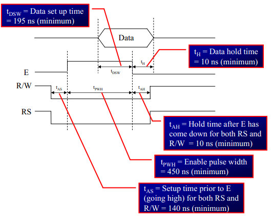
| − | } | + | ===Timing Diagram=== |
| | + | The below image shows the timing diagram for sending the data to the LCD.<br> |
| | + | As shown in the timing diagram the data is written after sending the RS and RW signals. It is still ok to send the data before these signals.<br> |
| | + | The only important thing is the data should be available on the databus before generating the High-to-Low pulse on EN pin. |
| | + | [[File:LCD CmdWrite.jpg|figure: command write]] |
| | + | <br><br> |
| | | | |
| | | | |
| | + | ===Steps for Sending Command:=== |
| | + | *step1: Send the I/P command to LCD. |
| | + | *step2: Select the Control Register by making RS low. |
| | + | *step3: Select Write operation making RW low. |
| | + | *step4: Send a High-to-Low pulse on Enable PIN with some delay_us. |
| | + | <html> |
| | + | <script src="https://gist.github.com/SaheblalBagwan/9e8c6f42511355062789a69cace9f980.js"></script> |
| | + | </html> |
| | + | <br><br> |
| | | | |
| | + | ===Steps for Sending Data:=== |
| | + | *step1: Send the character to LCD. |
| | + | *step2: Select the Data Register by making RS high. |
| | + | *step3: Select Write operation making RW low. |
| | + | *step4: Send a High-to-Low pulse on Enable PIN with some delay_us. |
| | + | The timings are similar as above only change is that '''RS''' is made high for selecting Data register. |
| | | | |
| | + | <html> |
| | + | <script src="https://gist.github.com/SaheblalBagwan/fd021a189be20644c37541d75de144e4.js"></script> |
| | + | </html> |
| | + | <br><br> |
| | | | |
| | + | =Hardware Connections= |
| | + | [[File:Lcd8bit.png]]<br> |
| | | | |
| − | /*---------------------------------------------------------------------------------
| + | = Code Examples = |
| − | LCD_DisplayRtcDate(char day,char month,char year)
| + | Here is the complete code for displaying the data on 2x16 LCD in 8-bit mode. |
| − | ----------------------------------------------------------------------------------
| + | <html> |
| − | * I/P Arguments: char day,char month,char year
| + | <script src="https://gist.github.com/SaheblalBagwan/1ac04a9ae5112efdbe338f994d7a1af3.js"></script> |
| − | day,month,year should be packed BCD format, as read from DS1307
| + | </html> |
| | + | <br><br> |
| | | | |
| − | * Return value : none
| + | =Using Explore Embedded Libraries := |
| | + | In the above tutorial we just discussed how to interface 2x16Lcd in 8-bit mode.<br> |
| | + | Once you know the working of lcd, you can directly use the ExploreEmbedded libraries to play around with your LCD.<br> |
| | + | For that you need to include the lcd.c/lcd.h and the associated files(delay/stdutils).<br> |
| | + | After including these files, the only thing you got to do is to configure the PORTs in lcd.h as per your hardware connection.<br> |
| | + | The below sample code shows how to use the already available LCD functions. |
| | | | |
| − | * description :This function display day,month,year read from DS1307.
| + | ==LCD 1x16== |
| | + | <html> |
| | + | <script src="https://gist.github.com/SaheblalBagwan/778c519d1babc5659c71086e81da0381.js"></script> |
| | + | </html> |
| | | | |
| − | ___________ Display the higher nibble of day after adding 0x30(ASCII conversion)
| + | ==LCD 2x16== |
| − | | Display the lower nibble of day after adding 0x30(ASCII conversion)
| + | <html> |
| − | |
| + | <script src="https://gist.github.com/SaheblalBagwan/f75119155d6e79321e222f8b611a6d34.js"></script> |
| − | | ________ Display the higher nibble of month after adding 0x30(ASCII conversion)
| + | </html> |
| − | | | Display the lower nibble of month after adding 0x30(ASCII conversion)
| + | |
| − | | |
| + | |
| − | | | _____ Display the higher nibble of year after adding 0x30(ASCII conversion)
| + | |
| − | | | | Display the lower nibble of year after adding 0x30(ASCII conversion)
| + | |
| − | | | |
| + | |
| − | 01/01/12 (1st-Jan 2012)
| + | |
| | | | |
| − | -----------------------------------------------------------------------------------*/
| + | ==LCD 4x20== |
| − | void LCD_DisplayRtcDate(char day,char month,char year)
| + | <html> |
| − | {
| + | <script src="https://gist.github.com/SaheblalBagwan/1b1a7846b1e0376f55bb5aedc8617dfe.js"></script> |
| − | LCD_DataWrite(((day>>4) & 0x0f) + 0x30);
| + | </html> |
| − | LCD_DataWrite((day & 0x0f) + 0x30);
| + | |
| − | LCD_DataWrite('/');
| + | |
| | | | |
| − | LCD_DataWrite(((month>>4) & 0x0f) + 0x30);
| + | [[FILE:01LCD 8bit.png]] |
| − | LCD_DataWrite((month & 0x0f) + 0x30);
| + | |
| − | LCD_DataWrite('/');
| + | |
| | | | |
| − | LCD_DataWrite(((year>>4) & 0x0f) + 0x30);
| + | =Downloads= |
| − | LCD_DataWrite((year & 0x0f) + 0x30);
| + | Download the sample code and design files from [https://github.com/ExploreEmbedded/8051_DevelopmentBoard this link]. |
| | | | |
| − | }
| |
| − | </syntaxhighlight>
| |
| − | }}
| |
| | | | |
| − | ==4 bit Mode==
| + | Have a opinion, suggestion , question or feedback about the article let it out here! |
| − | [[File:8051 LCD4BIT Interface.PNG|Fig 4: Schematic LCD 4 bit mode]]
| + | {{DISQUS}} |
In this tutorial we are going to see how to interface a 2x16 LCD with 8051 in 8-bit mode.
As per the name the 2x16 has 2 lines with 16 chars on each lines. It supports all the ascii chars and is basically used for displaying the alpha numeric characters. Here each character is displayed in a matrix of 5x7 pixels.
Apart from alpha numeric chars it also provides the provision to display the custom characters by creating the pattern.
Apart from the voltage supply connections the important pins from the programming perspective are the data lines(8-bit Data bus), Register select, Read/Write and Enable pin.
Data Bus: As shown in the above figure and table, an alpha numeric lcd has a 8-bit data bus referenced as D0-D7.
As it is a 8-bit data bus, we can send the data/cmd to LCD in bytes. It also provides the provision to send the the data/cmd in chunks of 4-bit, which is used when there are limited number of GPIO lines on the microcontroller.
Register Select(RS): The LCD has two register namely a Data register and Command register. Any data that needs to be displayed on the LCD has to be written to the data register of LCD. Command can be issued to LCD by writing it to Command register of LCD.
This signal is used to differentiate the data/cmd received by the LCD.
If the RS signal is LOW then the LCD interprets the 8-bit info as Command and writes it Command register and performs the action as per the command.
If the RS signal is HIGH then the LCD interprets the 8-bit info as data and copies it to data register. After that the LCD decodes the data for generating the 5x7 pattern and finally displays on the LCD.
Read/Write(RW): This signal is used to write the data/cmd to LCD and reads the busy flag of LCD.
For write operation the RW should be LOW and for read operation the R/W should be HIGH.
Enable(EN): This pin is used to send the enable trigger to LCD.
After sending the data/cmd, Selecting the data/cmd register, Selecting the Write operation. A HIGH-to-LOW pulse has to be send on this enable pin which will latch the info into the LCD register and triggers the LCD to act accordingly.
Below schematic shows the minimum connection required for interfacing the LCD with the microcontroller.
This section shows how to configure the GPIO for interfacing the LCD.
The below configuration is as per the above schematic. You can connect the LCD to any of the PORT pins available on your boards and update this section accordingly
In this section we are going to see how to send the data/cmd to the LCD along with the timing diagrams.
First lets see the timing diagram for sending the data and the command signals(RS,RW,EN), accordingly we write the algorithm and finally the code.
The below image shows the timing diagram for sending the data to the LCD.
As shown in the timing diagram the data is written after sending the RS and RW signals. It is still ok to send the data before these signals.
The only important thing is the data should be available on the databus before generating the High-to-Low pulse on EN pin.
In the above tutorial we just discussed how to interface 2x16Lcd in 8-bit mode.
Once you know the working of lcd, you can directly use the ExploreEmbedded libraries to play around with your LCD.
For that you need to include the lcd.c/lcd.h and the associated files(delay/stdutils).
After including these files, the only thing you got to do is to configure the PORTs in lcd.h as per your hardware connection.
The below sample code shows how to use the already available LCD functions.


