Difference between revisions of "6.8051 Interrupts"
| Line 6: | Line 6: | ||
=Basics= | =Basics= | ||
For the 8051 Microcontroller there are six interrupt sources as shown in the table below: | For the 8051 Microcontroller there are six interrupt sources as shown in the table below: | ||
| − | |||
}} | }} | ||
| + | {| class="wikitable" style="text-align:center;background-color:#87A96B;margin: 1em auto 1em auto;" | ||
| + | |+ Table. 1: Interrupt Vector Table | ||
| + | |- | ||
| + | !Interrupt||ROM Location(Hex)||Pin||Flag Clearing | ||
| + | |- | ||
| + | |Reset||0000||9||Auto | ||
| + | |- | ||
| + | |External HW Interrupt 0 (INT0)||0003||P3.2(12)||Auto | ||
| + | |- | ||
| + | |Timer 0 Interrupt(TF0)||000B||-||Auto | ||
| + | |- | ||
| + | |External HW Interrupt 1 (INT1)||0013||P3.3(13)||Auto | ||
| + | |- | ||
| + | |Timer 1 Interrupt(TF1)||001B||-||Auto | ||
| + | |- | ||
| + | |Serial Com Interrupt(RI and TI)||0023||-||Program SW | ||
| + | |} | ||
| + | |||
| + | |||
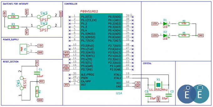
[http://exploreembedded.com/wiki/images/4/47/Schematic_8051Interupt.pdf '''Schematic'''] | [http://exploreembedded.com/wiki/images/4/47/Schematic_8051Interupt.pdf '''Schematic'''] | ||
[[File:8051Interupt.JPG|680px]] | [[File:8051Interupt.JPG|680px]] | ||
Revision as of 14:40, 1 August 2014
Intro
In this tutorial we will look at 8051 Interrupts. Interrupts are useful in many cases wherein the process simply wants to continue doing it's main job and other units(timers or external events) seek its attention when required. In other words the microcontroller, need not monitor the timers, the serial communication or the external pins P3.2 and P3.3. Whenever an event related to these units occur, it is informed to microcontroller with the help of interrupts.
Basics
For the 8051 Microcontroller there are six interrupt sources as shown in the table below:
| Interrupt | ROM Location(Hex) | Pin | Flag Clearing |
|---|---|---|---|
| Reset | 0000 | 9 | Auto |
| External HW Interrupt 0 (INT0) | 0003 | P3.2(12) | Auto |
| Timer 0 Interrupt(TF0) | 000B | - | Auto |
| External HW Interrupt 1 (INT1) | 0013 | P3.3(13) | Auto |
| Timer 1 Interrupt(TF1) | 001B | - | Auto |
| Serial Com Interrupt(RI and TI) | 0023 | - | Program SW |

