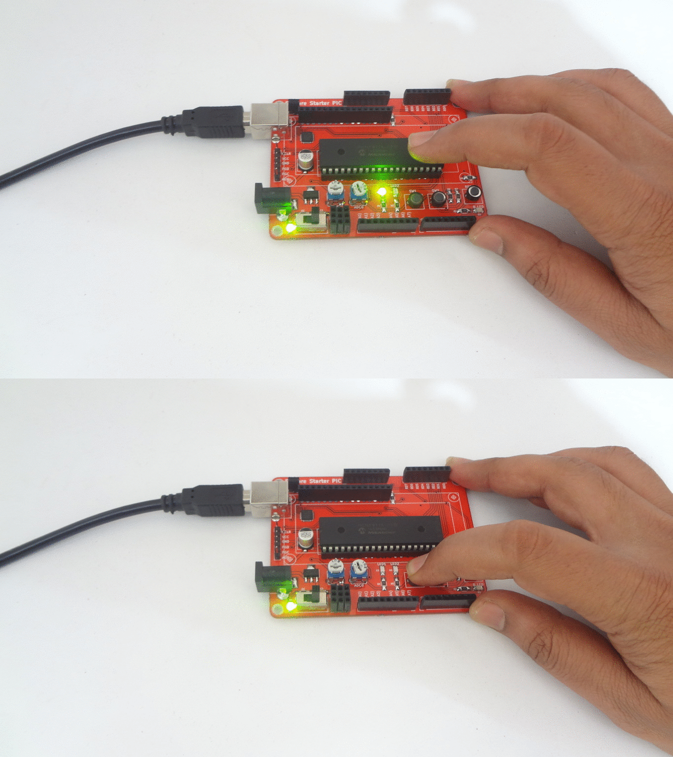
Switch and LED with PIC16F877A Starter Board
In this tutorial we will learn how to blink the LED's with PIC16F877 Starter Board.
The Explore Starter PIC board has two on board LED's which are connected to PORT D0 and PORT D1.
Steps
- Configure the PORTS as outputs using TRIS registers.
- Turn ON all the LEDs and wait for some time.
- Turn OFF all the LEDs and wait for some time.
Code
This file contains hidden or bidirectional Unicode text that may be interpreted or compiled differently than what appears below. To review, open the file in an editor that reveals hidden Unicode characters.
Learn more about bidirectional Unicode characters
#include "gpio.h" | |
#define LED PD_0 // Led is connected to PORTD.0 | |
#define SW1 PD_2 // Switch is connected to PORTD.2 | |
/* start the main program */ | |
void main() | |
{ | |
uint8_t value; | |
GPIO_PinDirection(SW1,INPUT); // Configure the switch pin as Input | |
GPIO_PinDirection(LED,OUTPUT); // Configure the Led pin as OUTPUT | |
while(1) | |
{ | |
value = GPIO_PinRead(SW1); // Read the switch status | |
GPIO_PinWrite(LED,value); // ON/OFF the led as per switch status | |
} | |
} |