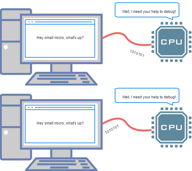
An embedded project/product without a Universal Asynchrounous Receiver Transmiter (UART) interface is unimaginable. Even if the MCU is not talking to another serial device, you'll need it at-least during the development work to speak to your computer. UART also come in handy for firmware upgrade and enabling/disabling product features during it's lifetime. This probably one of the first interfaces you would want to include in your project.
So let's get started! As with the series, we will be using a Atmega32 for this tutorial, other AVRs should work the same way. Do do not forget to look at the datasheet once before trying out with other controllers.
Basics
I know you're getting your head around the acronym UART still, but do not worry it is simple. Don't know where the word Universal came from but, Asynchronous makes lot of sense. Figure below shows the typical connection of a serial device with the MCU. There are basically Transmit(Tx) and Receive(Rx) lines and a common ground.
Now imagine we want to send some data as shown below:
The duration of a '1' or '0' is unknown to the receiving device. Hence it asynchronous. This is solved by agreeing upon a common data rate by both the devices, known as baud Rate.
You'll find typical baud rates to be 4800, 9600, 19200, 115200 etc. Atmega32 allows you to select the baud rate you wish. You need to look at the baud rate of the interfacing device to know it's default value. Typically most devices are set to 9600. Do not take my word for it, do check the datasheet.
Let us go ahead and configure the Atmega32 Hardware UART to communicate with the computer and send/receive data strings.


