Interfacing KS0108 based JHD12864E Graphics LCD with Atmega32
In this tutorial we will look at interfacing KS0108 display controller based JHD12864E display. There are many displays out there based on KS0108 or compatible display controller. They all work the same way, but make sure to check the datasheet for the pin diagram because the pin layout is not uniform, if you've a display from different manufacturer. We will look at the working of the display, the hardware setup and programming with ATmega32. You may use any other AVR MCU as well. You may port the library for other MCUs as well. We have it tested and working on 8051 PIC and ARM. We may do a similar tutorial on these MCUs as well. Unlike a 16 x 2 display, this does not have a character map for ascii values stored on its ROM. However it allows us the flexibility of creating fonts like Arial, times new roman etc. We could also display bit-map images on it and stretching it little further we can make GUI's and little animation, but that's for another day. So lets get started.
Contents
Working of KS0108 Display Controller
The image tells the story of the a 128 x 64 display. The display that we used for the tutorial is JHD12864E and it has two KS0108 controllers in built. Each controller controls 64 x 64 pixels. Hence the display is 128 pixels wide and 64 pixels in height.
Each pixel is either ON(black) or OFF(green), a monochrome display indeed.
- The entire display is divided into 2 pages.
- Each page has 64 x 64 pixels.
- Each page in-turn is divided into 8 lines.
- Each line has I do not know what to say. It has 64 columns and each column is 8 pixel tall. We have decided to call it the cursor position.
- Now when you write a byte to the LCD from the micro-controller it is displayed on that column as marked by * in the image.
If you've read and followed what is written above, make the image below full screen and observe it carefully. It has taken me an hour to make that image.
Instruction Set
If you've used a 16x2 displayed, this works exactly like it. However note that there is no ROM on this LCD. Hence the ASCII character patterns are not stored any where. We can make character fonts as we wish. If you download the code, you'll see we have implemented all the characters with 5x8 pixel font.
- Command Write: Used to set cursor line positions and set up the display.
- Data Write: Writes a byte on the display as discussed earlier.
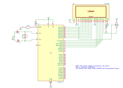
Schematic and HW Setup
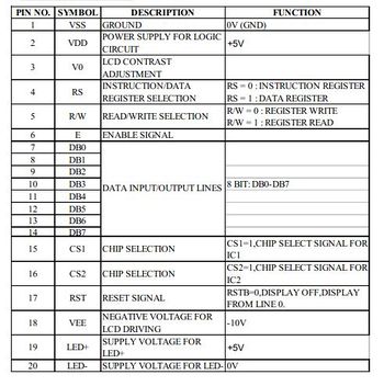
Pin Description
I know all the pins are self explanatory. However not the pin number 18. It generates negative voltage required for the display. A 10K ohm pot is connected as shown in the circuit to generate -10V.


