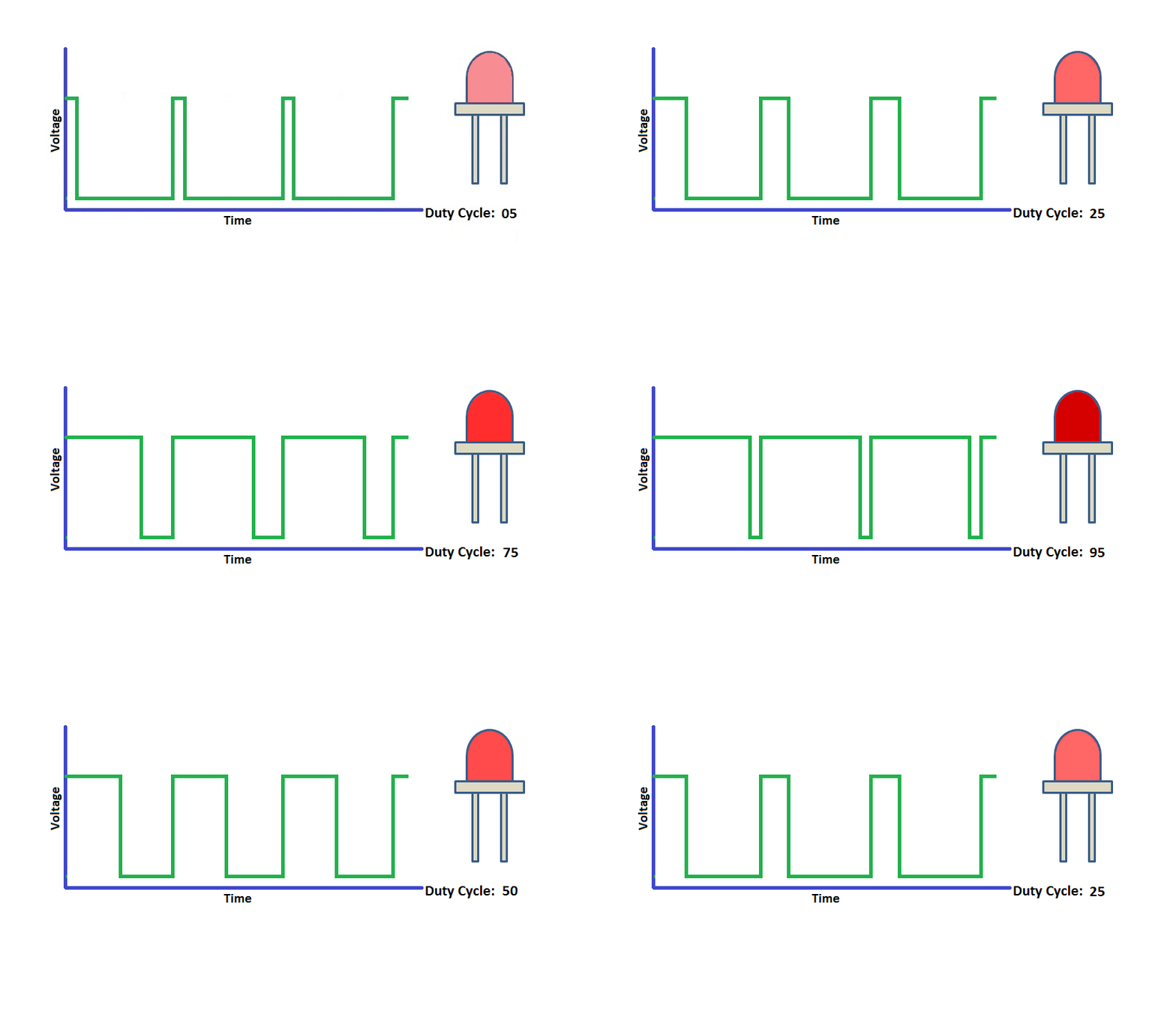
In this tutorial we will see how to generate the PWM signals using PIC16F877A.

Prerequisites
Please check this tutorial for detailed explanation on PIC16F877A PWM module.
PIC16F877A PWM Module
PIC16F877A microcontroller has two independent CCP(Capture/Compare/PWM) modules, named as CCP1 and CCP2. Each CCP module has two 8-bit resistors(CCPxH,CCPxL) that can be use as:
- 16 bit Capture Register
- 16 bit Compare Register
- 10-bit PWM Register.
In this tutorial we will be discussing only the PWM part of CCP. PIC has 2PWM module with a resolution of 10-bits.
Below tables shows the PWM module of PIC.
| PWM Channel | Port Pin | Control Register | Duty Cycle Register | Period Register |
|---|---|---|---|---|
| PWM1 | PC.2 | CCP1CON | CCPR1L | PR2 |
| PWM2 | PC.1 | CCP2CON | CCPR2L | PR2 |
Code1
Below is the example to vary the brightness of the LED using PWM.
Code
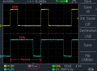
Progarm to generate the PWM signals of 25% & 75% duty cycle.

