Interfacing Seven Segment Display with AVR Breakout
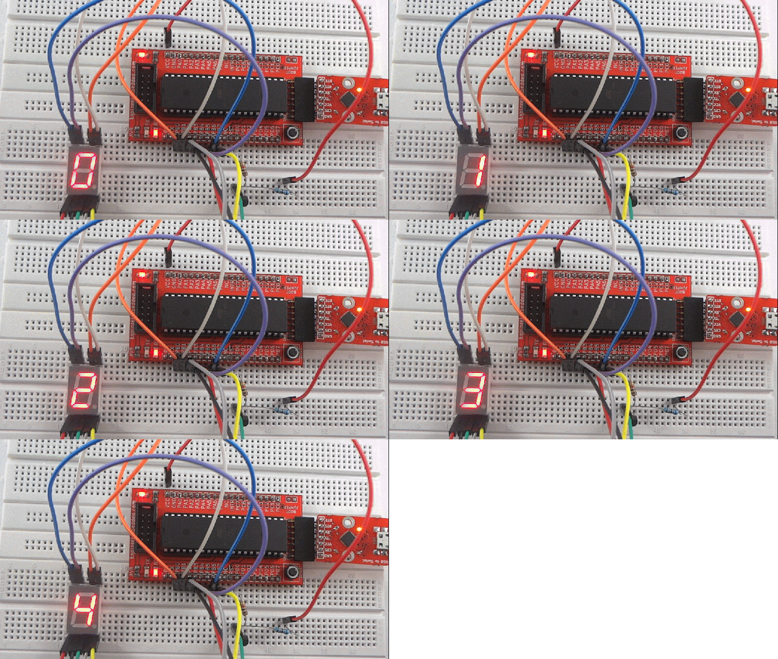
After blinking the LED , Let's display user information like numeric value using seven segment display. In this tutorial we will interface a seven segment display to AVR breakout board and display a single digit hex (0-F).
Contents
Basics
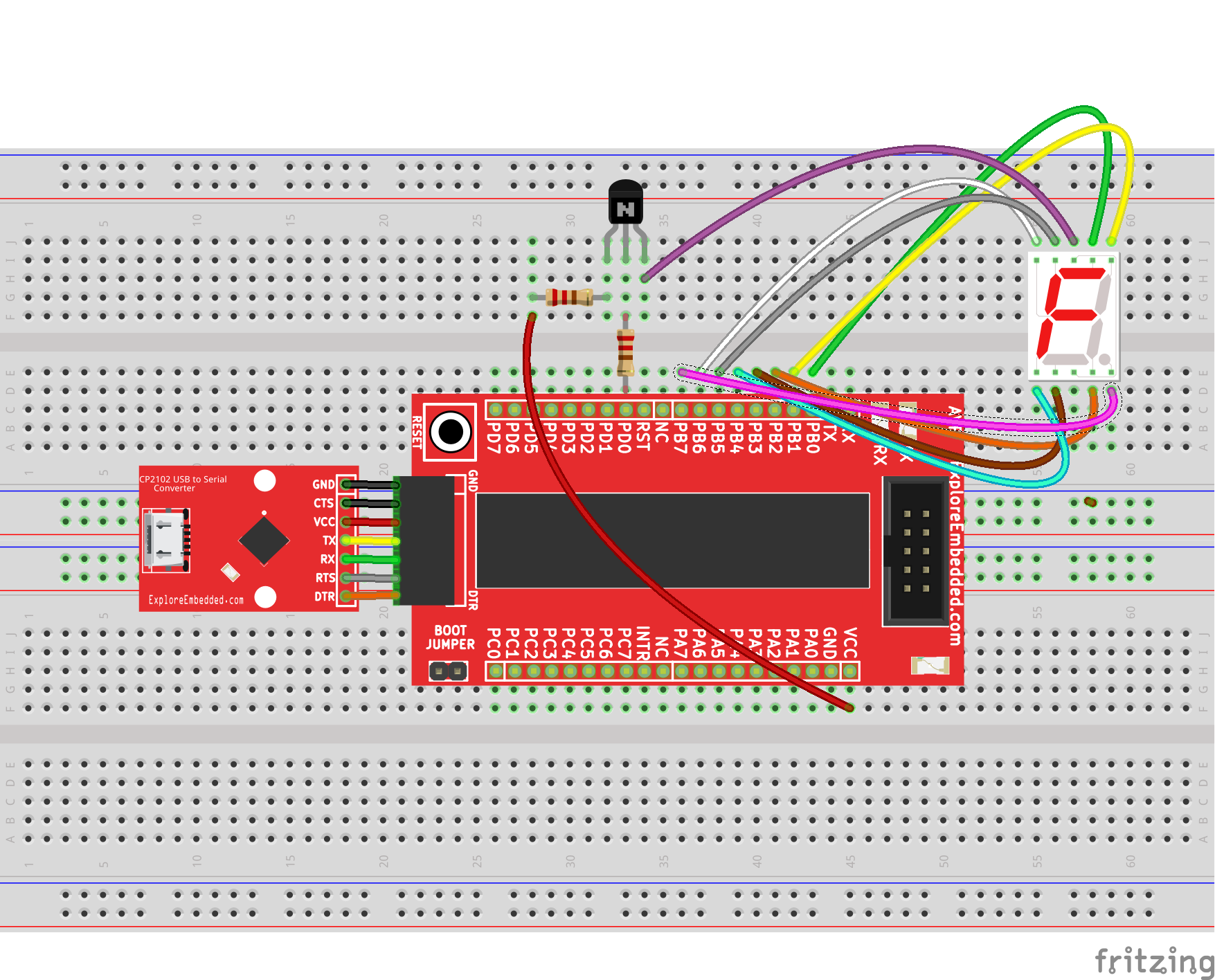
For this tutorial we are using common anode seven segment display. To drive this display we require a BC 547 transistor. The PORT B is connected to data lines of the display and PORT D0 is connacted to base of the transistor through 1k ohm resistor and collector is connected to VCC through 68 ohm resistor as shown in hook up.
check out Interfacing Seven Segment Displays with AVR tutorial for basics of seven segment display.
Hook Up
Code


