


.JPG)
.JPG)
.JPG)
.JPG)
- Robotics board based on Atmega8 MCU.
- Sensor shield to make line follower, light follower and obstacle avoidance robot.
- Inbuilt DTMF decoder (MT8870) to make a Mobile controlled Robot
- USB to UART convertor (CP2102) for communicating with computer, make a computer controlled Robot.
- MCU with bootloader, no external programmer required.
- Compatible with Arduino Software.
- Electronics
- Robotics Board Based on Atmega8, with L293D driver and MT8870 DTMF Decoder
- Sensor Sheild for line, light and obstacle detecting robots
- Mechanical
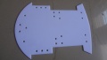
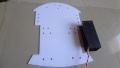
- Chasis(Red and White Basis)
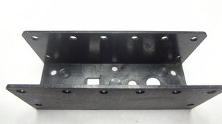
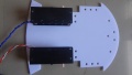
- BO Motor Clamps
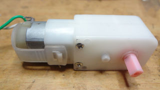
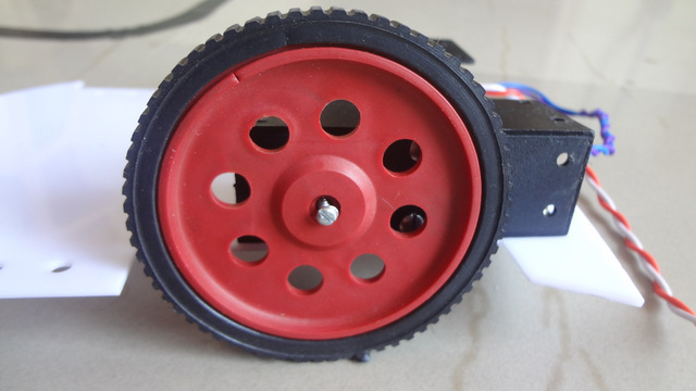
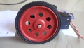
- DC BO Motors 150 RPM
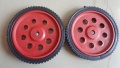
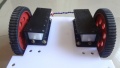
- Wheels x2
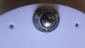
- Castor Wheel
- Screws
- Battery Holder x2
- Other
- USB Cable
- 5 Pin Sensor cable
Mechanical
Assembling the Robot
Quick Video
Mounting the BO Motor with Clamps

Step 1
Step 2
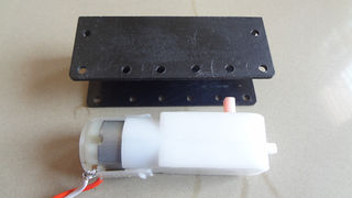
Step 3
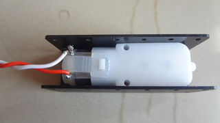
Step 4

Step 5
Step 6
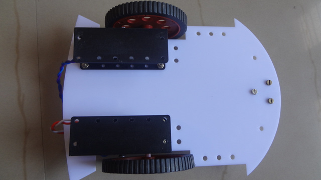
Attaching Wheels to chasis
Step 1
Step 2
Step 3
Step 4
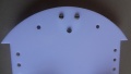
Assembling the Base
Step 1
Step 2
Step 3
Step 4
Electronics
Robo Controller Board
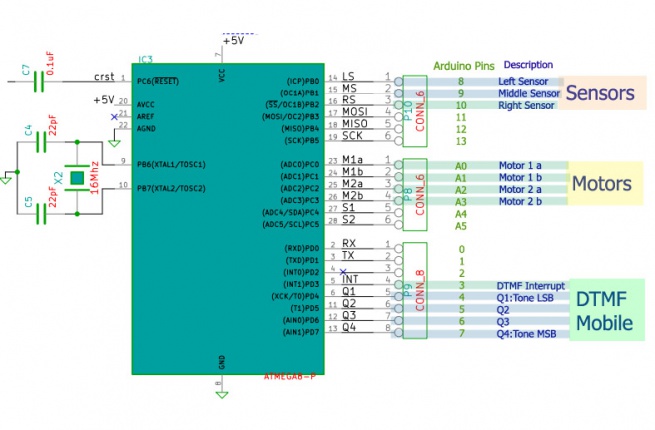
- The Robo Board: This is the heart of the robot. The board has following ICs
- Motor Driver: A L293D Motor driver on board is used to control the two driving motors of the Robot
- DTMF Decoder: A MT8870 or compatible IC is used to convert DTMF mobile tones to digits, which helps in making Mobile controlled Robot
- Microcontroller: The board feature a Atmega8 (Atmega328 can also be used) controller. Figure below shows the way in which various units are connected to the microcontroller.
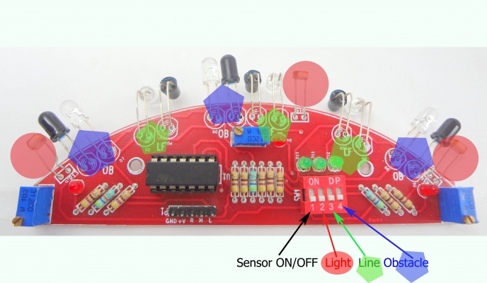
Sensor Sheild
The sensor sheild has a comparator IC that gives logical high when any of the right, Middle or left sensors are detected.The sensor sheild has following sensors:
- 3 IR pairs for line following
- 3 IR Pairs for obstacle avoidance
- 3 Light Dependent Resistors
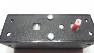
Notice the DIP switch shown in the image below, it used to select the above three sensor options.
Downloads
[1]
Robo_Board Schematic
Sensor Sheild Schematic
Bootloader: optiboot
The Explore Robo uses optiboot. Find the modified source code here. Fuse settings on Explore Robo:
L FUSE H FUSE LOCK 0xFF 0xDC 0xCF Fuse bit details *Do not modify fuse bits unless you're sure of what you're doing!
Programming
Using the Board with AVR Studio and Flashing with XploreFlash
Step 1: Xplore flash is based on various opensource software, it requires avrdude. Avrdude is part of WinAVR GCC complier. Download and install it.Step 2:To connect Development board with computer USB driver is required. Windows USB to UART Drivers for CP2102
- For Other Operating system please download from Silicon Labs website.
Step 3: Download and install XploreFlash GUI. (XploreFlash GUI is based on AVRDUDESS)
Step 4: Follow the steps on images below to flash the board.
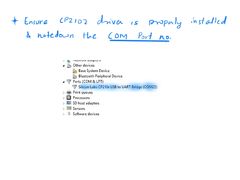
Check for COM port
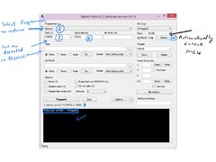
Hit Detect MCU
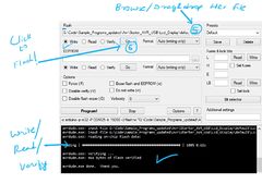
Browse file and Flash
Note: The GUI software will require .NET framework 2.0 or later please download and install it.
Using the Board with Arduino Software
->For the board to appear in the arduino software add the following lines in the boards.txt file.
File location:e.g: C:\Program Files\Arduino\hardware\arduino#################################################
atmega8.name=Explore Robo w/ ATmega8
atmega8.upload.protocol=arduino
atmega8.upload.maximum_size=7168
atmega8.upload.speed=19200
atmega8.bootloader.low_fuses=0xdf
atmega8.bootloader.high_fuses=0xca
atmega8.bootloader.path=atmega8
atmega8.bootloader.file=ATmegaBOOT-prod-firmware-2009-11-07.hex
atmega8.bootloader.unlock_bits=0x3F
atmega8.bootloader.lock_bits=0x0F
atmega8.build.mcu=atmega8
atmega8.build.f_cpu=16000000L
atmega8.build.core=arduino
atmega8.build.variant=standard
Steps
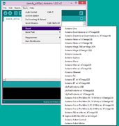
1.The board shows up in arduino software
2.Check exact COM port
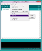
3.Select the COM port.
Arduino Examples


