Difference between revisions of "PIC16f877a Timer"
| Line 35: | Line 35: | ||
*Interrupt on overflow from FFh to 00h | *Interrupt on overflow from FFh to 00h | ||
*Edge select for external clock | *Edge select for external clock | ||
| + | <br><br> | ||
| + | |||
| + | =Timer0 Registers= | ||
| + | The below table shows the registers associated with PIC16f877A Timer0 module.<br> | ||
| + | {| class="table table-striped table-hover table-condensed table-bordered" | ||
| + | |-class="info" | ||
| + | !Register || Description | ||
| + | |- | ||
| + | |OPTION_REG|| This registers is used to configure the TIMER0 Prescalar,Clock Source etc | ||
| + | |- | ||
| + | |TMR0 || This register hold the timer count value which will be incremented depending on prescalar configuration | ||
| + | |- | ||
| + | |INTCON|| This register contains the Timer0 overflow flag(TMR0IF) and corresponding Inetrrupt Enable flag(TMR0IE). | ||
| + | |} | ||
=TImer Reg= | =TImer Reg= | ||
Revision as of 15:24, 6 May 2016
In this tutorial we are going to discuss the Timer module of Pic16f877a.
First we will see what are timers, their working and later we will configure the PIC16f877a timers to generate delay of 100ms and 500ms respectively. At the end we will see how to use the ExploreEmdedded Timer library.
Timer Basics
As the name suggests these are used to measure the time or generate the accurate time delay. The microcontroller can also generate/measure the required time delays by running loops, but the timer/counter peripheral relieves the CPU from that redundant and repetitive task, allowing it to allocate maximum processing time for other tasks.
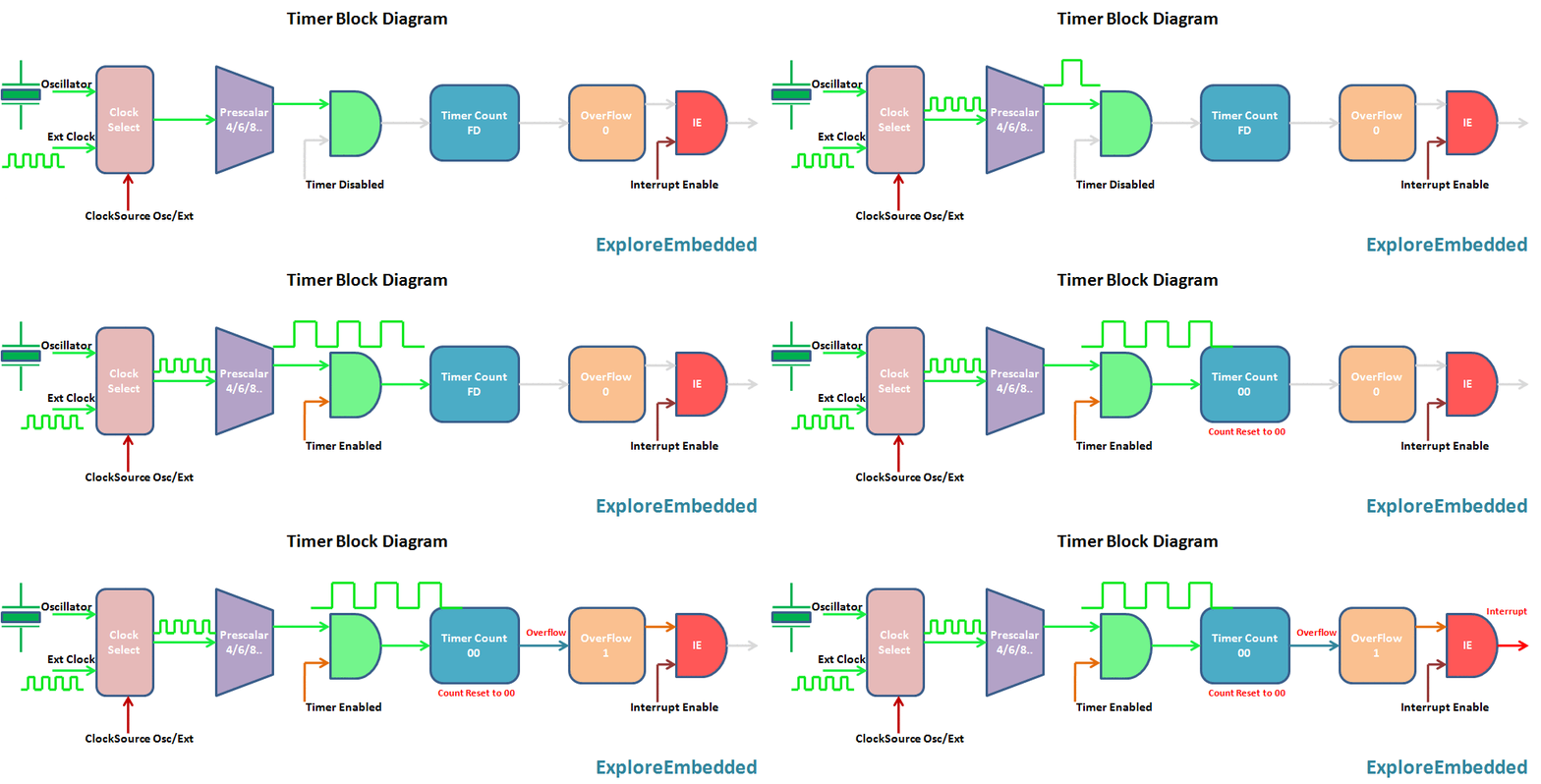
Timer is nothing but a simple binary counter that can be configured to count clock pulses(Internal/External). Once it reaches the Max value, it will roll back to zero setting up an OverFlow flag and generates the interrupt if enabled.

PIC Timer Module
Pic16f877a has three indepenndent timer which can be used as timer,Counters or for PWM generation.
Below table provides the details of the three Timers.
| Timer | Size | Control Register | Count Register | Min Delay | Max Delay |
|---|---|---|---|---|---|
| TIMER0 | 8-bit | T0CON | TMR0 | 0 | 0 |
| TIMER1 | 16-bit | T1CON | TMR1H,TMR1L | 0 | 0 |
| TIMER2 | 8-bit | T2CON | TMR2 | 0 | 0 |
Timer 0
The timer TMR0 module is an 8-bit timer/counter with the following features:
- 8-bit timer/counter
- Readable and writable
- 8-bit software programmable prescaler
- Internal or external clock select
- Interrupt on overflow from FFh to 00h
- Edge select for external clock
Timer0 Registers
The below table shows the registers associated with PIC16f877A Timer0 module.
| Register | Description |
|---|---|
| OPTION_REG | This registers is used to configure the TIMER0 Prescalar,Clock Source etc |
| TMR0 | This register hold the timer count value which will be incremented depending on prescalar configuration |
| INTCON | This register contains the Timer0 overflow flag(TMR0IF) and corresponding Inetrrupt Enable flag(TMR0IE). |

