Difference between revisions of "Uploading .bin file to ExploreM3"
(Created page with "Category:Explore M3 Bare Metal") |
|||
| Line 1: | Line 1: | ||
[[Category:Explore M3 Bare Metal]] | [[Category:Explore M3 Bare Metal]] | ||
| + | In this tutorial we will be discussing how to upload the .hex and .bin files to Lpc1768 board.<br> | ||
| + | For flashing the hex files, we will be using the flash magic software along with a Usb to Serial converter.<br> To upload the .bin, no external hardware is required but board should have the secondary boot loader.<br><br><br> | ||
| + | |||
| + | =Generating .hex File= | ||
| + | Check the tutoial [[LPC1768: Keil Project For Hex File|LPC1768 Keil Setup]] for generating the .hex file using keil.<br><br><br> | ||
| + | |||
| + | =.Hex Using Flash Magic= | ||
| + | You need a USB to Serial(UART) convertor in order to get this working. The neat thing about the NXP controllers is, they come with a UART boot-loader from the factory. | ||
| + | [[File:FlashMagicConnection.jpg|x400px]] | ||
| + | <br><br> | ||
| + | |||
| + | [[File:Lpc1768_Usb2Serial.jpg|x400px]] | ||
| + | |||
| + | |||
| + | Note: If your converter does not have DTR and RTS lines, "hold down the ISP/PRI_BLD switch, RESET the board(press and release reset switch) and then release the ISP switch ". Now the Boot Contoller will be in ISP/PRI_BLD mode and you can flash the hex file using flash magic.<br><br> | ||
| + | |||
| + | Now open the flash magic software and follow the below steps. | ||
| + | #Select the IC from Select Menu. | ||
| + | #Select the COM Port. <b>Check the device manger for detected Com port</b>. | ||
| + | #Select Baud rate from 9600-115200 | ||
| + | #Select None Isp Option. | ||
| + | #Oscillator Freq 12.000000(12Mhz). | ||
| + | #Check the Erase blocks used by Hex file option | ||
| + | #Browse and Select the hex file. | ||
| + | #Check the Verify After Programming Option. | ||
| + | #If DTR and RTS are used then go to Options->Advanced Options-> Hardware Config and select the Use DTR and RTS Option. | ||
| + | #Hit the Start Button to flash the hex file. | ||
| + | #Once the hex file is flashed, Reset the board. Now the controller should run your application code.<br><br> | ||
| + | |||
| + | [[File:0_Lpc1768FlashMagic.jpg|x400px]] | ||
| + | <br><br><br> | ||
| + | ---- | ||
| + | =Generating .bin File= | ||
| + | Check this tutoial [[LPC1768: Keil Project For Bin File|LPC1768 Keil Setup]] for generating the .bin file using keil.<br><br><br> | ||
| + | |||
| + | =.Bin File Using Secondary Boot Loader= | ||
| + | For uploading the .bin file, secondary(USB) boot-loader needs to be flashed to the controller. Even though we put a USB boot-loader, the serial boot-loader will be still present to flash the hex files using Flash Magic. | ||
| + | |||
| + | Follow the below steps to upload the new .bin file to LPC1768 board: | ||
| + | #Connect the USB Jumpers. | ||
| + | #Connect the ExploreLpc1768 to system using a USB cable. | ||
| + | #Hold the USB_Btlr switch. | ||
| + | #Press the Reset Switch. | ||
| + | #Release the Reset Switch. | ||
| + | #Release the USB_Btlr switch. | ||
| + | #Now the board will be detected as Explore1768. | ||
| + | #Delete the old firmware.bin file. | ||
| + | #Paste the new .bin file. | ||
| + | #Reset the Board. | ||
| + | #Now your Application code should be running on the board.<br><br> | ||
| + | |||
| + | [[File:LPc1768_UsbBootLoader.jpg|x400px]] | ||
| + | <br><br><br> | ||
| + | |||
| + | Have a opinion, suggestion , question or feedback about the article let it out here! | ||
| + | {{DISQUS}} | ||
Revision as of 17:38, 23 April 2016
In this tutorial we will be discussing how to upload the .hex and .bin files to Lpc1768 board.
For flashing the hex files, we will be using the flash magic software along with a Usb to Serial converter.
To upload the .bin, no external hardware is required but board should have the secondary boot loader.
Contents
Generating .hex File
Check the tutoial LPC1768 Keil Setup for generating the .hex file using keil.
.Hex Using Flash Magic
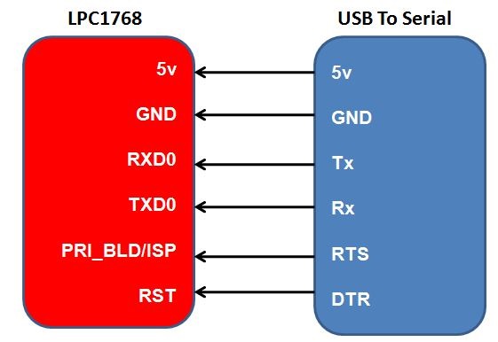
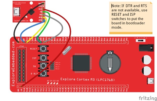
You need a USB to Serial(UART) convertor in order to get this working. The neat thing about the NXP controllers is, they come with a UART boot-loader from the factory.

Note: If your converter does not have DTR and RTS lines, "hold down the ISP/PRI_BLD switch, RESET the board(press and release reset switch) and then release the ISP switch ". Now the Boot Contoller will be in ISP/PRI_BLD mode and you can flash the hex file using flash magic.
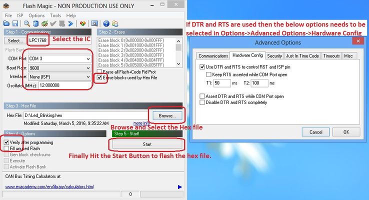
Now open the flash magic software and follow the below steps.
- Select the IC from Select Menu.
- Select the COM Port. Check the device manger for detected Com port.
- Select Baud rate from 9600-115200
- Select None Isp Option.
- Oscillator Freq 12.000000(12Mhz).
- Check the Erase blocks used by Hex file option
- Browse and Select the hex file.
- Check the Verify After Programming Option.
- If DTR and RTS are used then go to Options->Advanced Options-> Hardware Config and select the Use DTR and RTS Option.
- Hit the Start Button to flash the hex file.
- Once the hex file is flashed, Reset the board. Now the controller should run your application code.
Generating .bin File
Check this tutoial LPC1768 Keil Setup for generating the .bin file using keil.
.Bin File Using Secondary Boot Loader
For uploading the .bin file, secondary(USB) boot-loader needs to be flashed to the controller. Even though we put a USB boot-loader, the serial boot-loader will be still present to flash the hex files using Flash Magic.
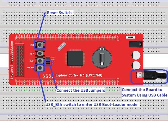
Follow the below steps to upload the new .bin file to LPC1768 board:
- Connect the USB Jumpers.
- Connect the ExploreLpc1768 to system using a USB cable.
- Hold the USB_Btlr switch.
- Press the Reset Switch.
- Release the Reset Switch.
- Release the USB_Btlr switch.
- Now the board will be detected as Explore1768.
- Delete the old firmware.bin file.
- Paste the new .bin file.
- Reset the Board.
- Now your Application code should be running on the board.
Have a opinion, suggestion , question or feedback about the article let it out here!


