Difference between revisions of "Switch and a LED with AVR Breakout"
| Line 18: | Line 18: | ||
=Downloads= | =Downloads= | ||
| + | Download the complete project folder from the below link: | ||
| + | https://github.com/ExploreEmbedded/AVR-MCU-Breakout-Board/archive/master.zip<br> | ||
| + | |||
| + | |||
| + | |||
| + | Have a opinion, suggestion , question or feedback about the article let it out here! | ||
{{DISQUS}} | {{DISQUS}} | ||
Latest revision as of 10:18, 20 April 2016
Now we will control the LED depending on external input. In this tutorial we will interface a switch to one of the port pin and display its status on LED connected to other port.
Contents
Basics
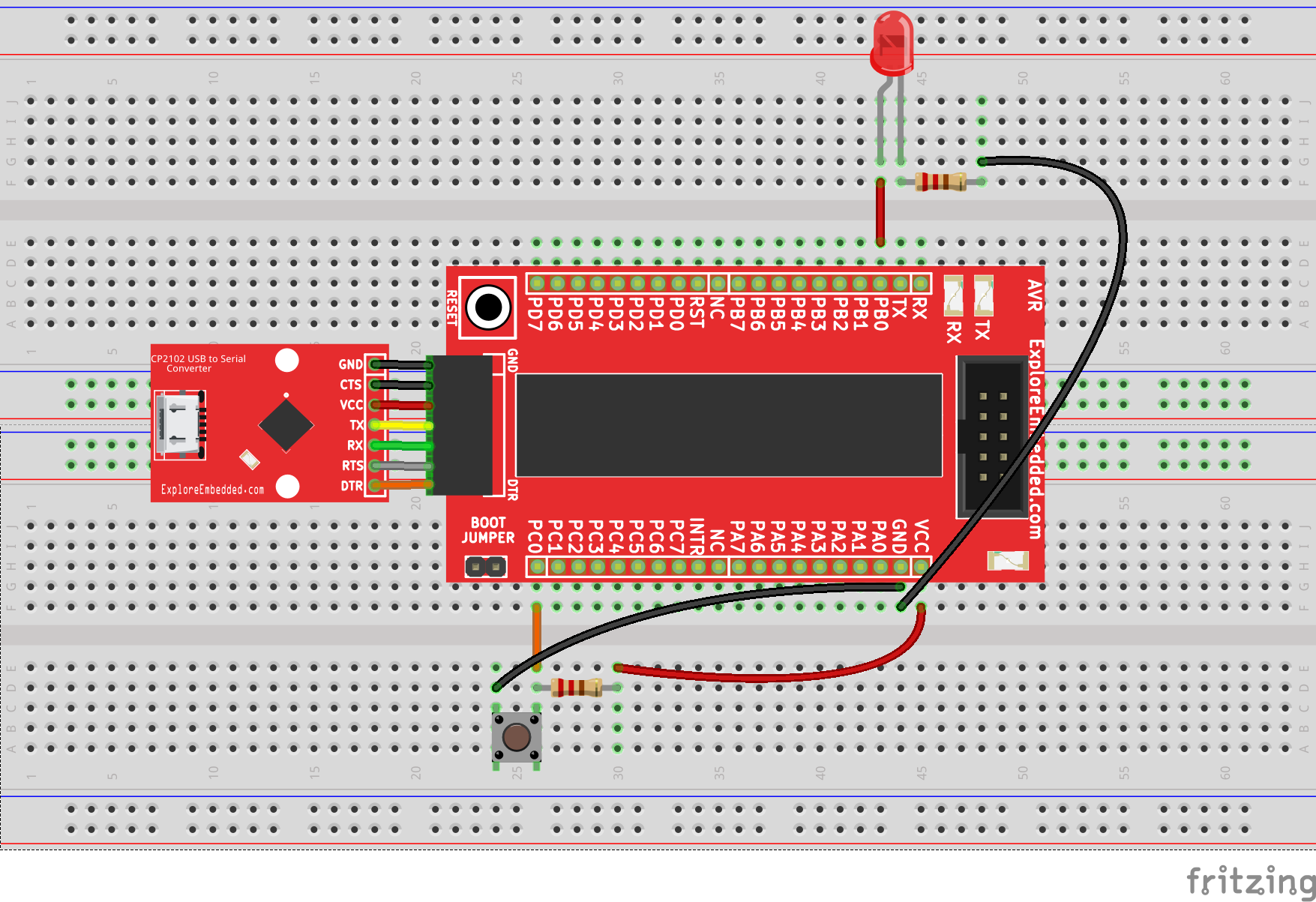
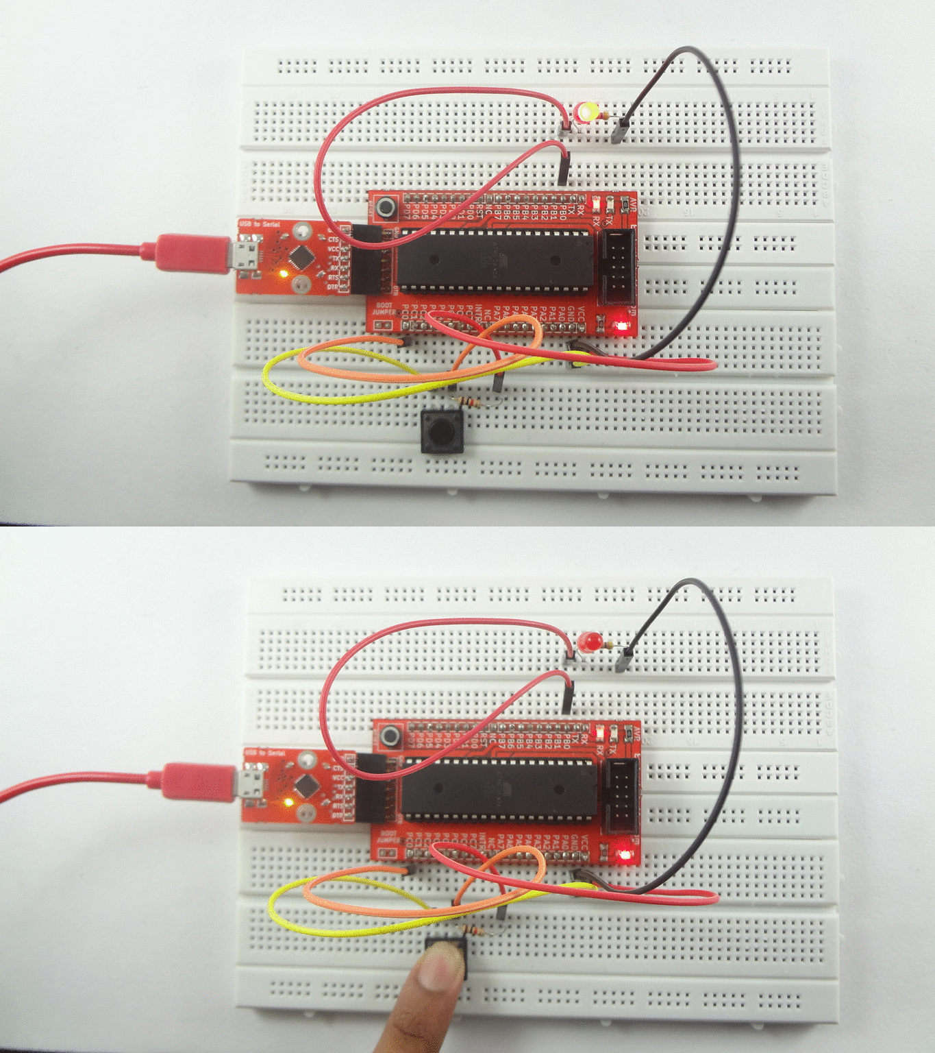
For this tutorial we will a connect a switch to PORT C0 and LED to PORT B0 of Atmega32. W will configure PORT A0 as input to read the switch status and PORT C0 as outputto display the switch status on LED. Initially LED will be ON , when we press switch the LED will be OFF.
Refer the AVR I/O Register Configuration tutorial for basics of GPIO register configuration.
Hook Up
Code
Demo
Downloads
Download the complete project folder from the below link:
https://github.com/ExploreEmbedded/AVR-MCU-Breakout-Board/archive/master.zip
Have a opinion, suggestion , question or feedback about the article let it out here!


