Difference between revisions of "Interfacing LCDs with AVR Breakout"
| Line 65: | Line 65: | ||
<br> | <br> | ||
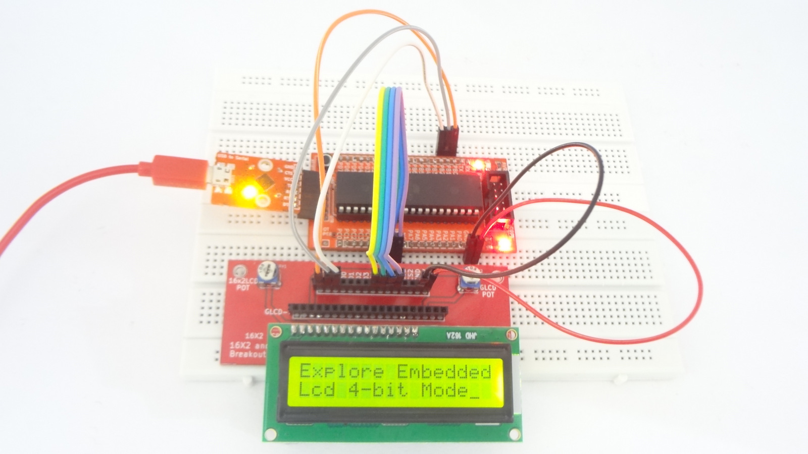
[[file:0_16x2lcd.JPG|16x2 LCD]] | [[file:0_16x2lcd.JPG|16x2 LCD]] | ||
| − | <gallery | + | <gallery> |
file:lcd16x1_avr.JPG|16x1 LCD | file:lcd16x1_avr.JPG|16x1 LCD | ||
file:lcd20x4_avr.JPG|20x4 LCD | file:lcd20x4_avr.JPG|20x4 LCD | ||
Revision as of 17:53, 1 April 2016
In this tutorial let's interface a 16x1,16x2 and 20x4 character display with AVR breakout board. For this tutorial we will require a LCD Breakout.
Basics
LCD can be interfaced with AVR breakout in two modes i.e. 8 bit and 4 bit. Let's
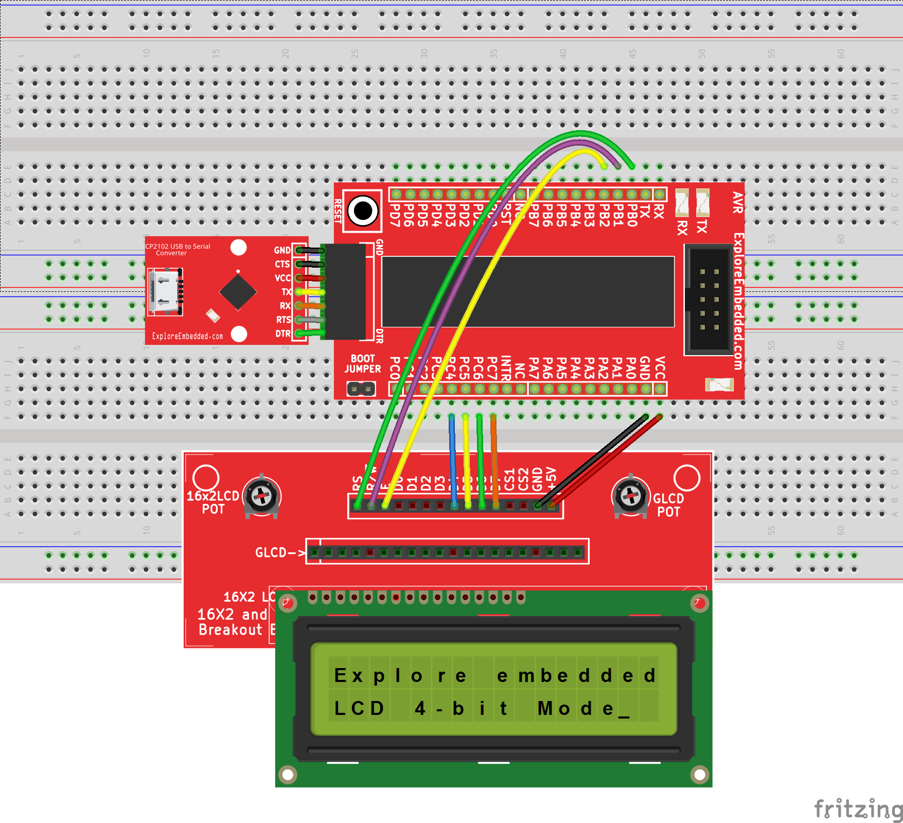
interface it in 4 bit mode.We will connect the display in 4 bit mode. You can change it to 8 bit mode making changes in connections and corresponding code. Hardware connections remain same for LCD 16x1,16x2,20x4 as shown in hook up.
Refer 8051 Tutorial for basics of character LCDs
Hook Up
Code
LCD 16 x 1
#include "lcd.h"
int main()
{
    /*Connect RS->PB0, RW->PB1, EN->PB2 and data bus to PORTC.4 to PORTC.7*/
    LCD_SetUp(PB_0,PB_1,PB_2,P_NC,P_NC,P_NC,P_NC,PC_4,PC_5,PC_6,PC_7);
    LCD_Init(1,16);
    LCD_DisplayString("Explore");
    while(1);
    return (0);
}
LCD 16 x 2
#include "lcd.h"
int main()
{
    /*Connect RS->PB0, RW->PB1, EN->PB2 and data bus to PORTC.4 to PORTC.7*/
    LCD_SetUp(PB_0,PB_1,PB_2,P_NC,P_NC,P_NC,P_NC,PC_4,PC_5,PC_6,PC_7);
    LCD_Init(2,16);

    LCD_DisplayString("Explore Embedded");
    LCD_DisplayString("Lcd 4-bit Mode");
    while(1);

    return (0);
}
LCD 20 x 4
#include "lcd.h"
int main()
{
    /*Connect RS->PB0, RW->PB1, EN->PB2 and data bus to PORTC.4 to PORTC.7*/
    LCD_SetUp(PB_0,PB_1,PB_2,P_NC,P_NC,P_NC,P_NC,PC_4,PC_5,PC_6,PC_7);
    LCD_Init(4,20);

    LCD_DisplayString("Explore Embedded\n");
    LCD_DisplayString("LCD 4-bit Mode\n");
    LCD_DisplayString("20 x 4 \n");
    LCD_DisplayString(":)  :O");

    while(1);

    return (0);
}


