Difference between revisions of "LPC1768: GLCD Interfacing"
m |
m |
||
| Line 72: | Line 72: | ||
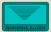
[[File:Glcd horizontial line.png|frameless]] | [[File:Glcd horizontial line.png|frameless]] | ||
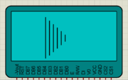
| − | [[File:Glcd | + | [[File:Glcd verticl line.png|frameless]] |
[[File:Glcd line.png|frameless]] | [[File:Glcd line.png|frameless]] | ||
[[File:Glcd rectangle.png|frameless]] | [[File:Glcd rectangle.png|frameless]] | ||
| − | [[File:Glcd fill | + | [[File:Glcd fill rectangle.png|frameless]] |
[[File:Glcd cirlce.png|frameless]] | [[File:Glcd cirlce.png|frameless]] | ||
[[File:Glcd fill circle.png|frameless]] | [[File:Glcd fill circle.png|frameless]] | ||
Revision as of 19:08, 15 June 2015
Contents
Intro
If you have done with simple 16x2 LCD and still want to do more with display, its time to have fun with Graphics LCD.
We all really enjoy animations kind of things and this is the stuff what we can do with GLCD.
GLCD is very similar to simple 16x2 LCD with additional features. To explore these features and functionality you would like to see our tutorial Graphics LCD Basics : KS0108 based JHD12864E
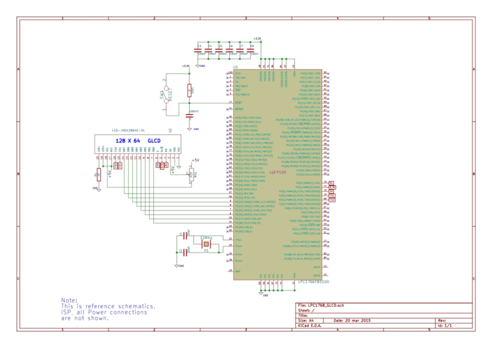
Schematic
Port Connection
This section shows how to configure the GPIO for interfacing the GLCD.
The below configuration is as per the above schematic. You can connect the GLCD to any of the PORT pins available on your boards and update this section accordingly
GLCD Operation
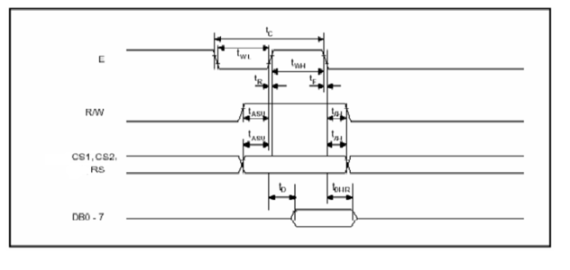
In this section we are going to see how to send the data/cmd to the GLCD along with the timing diagrams. First lets see the timing diagram for sending the data and the command signals(RS,RW,EN), accordingly we write the algorithm and finally the code.
Timing Diagram
The below image shows the timing diagram for sending the data to the GLCD.
As shown in the timing diagram the data is written after sending the RS and RW signals. It is still ok to send the data before these signals.
The only important thing is the data should be available on the databus before generating the High-to-Low pulse on EN pin.
Steps for Sending Command:
- step1: Send the I/P command to GLCD.
- step2: Select the Control Register by making RS low.
- step3: Select Write operation making RW low.
- step4: Send a High-to-Low pulse on Enable PIN with some delay_us.
Steps for Sending Data:
- step1: Send the character to GLCD.
- step2: Select the Data Register by making RS high.
- step3: Select Write operation making RW low.
- step4: Send a High-to-Low pulse on Enable PIN with some delay_us.
The timings are similar as above only change is that RS is made high for selecting Data register.
Code Example
Example 1
Let's start with displaying some text.
Using Explore Embedded Libraries :
In the above example we just discussed how to interface Graphics Lcd.
Once you know the working of GLCD, you can directly use the ExploreEmbedded libraries to play around with your GLCD.
For that you need to include the glcd.c/glcd.h and the associated files(delay/stdutils).
The below sample code shows how to use the already available GLCD functions.
Refer this link for more info on GLCD libraries.
Graphics Library
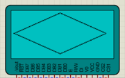
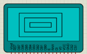
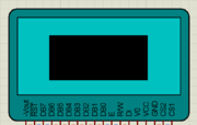
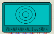
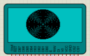 Lots of things are there which you would like to do with GLCD and we will cover it in the future tutorials. For now, you don't forget to comment.

