Difference between revisions of "Keil Setup For 8051"
| Line 1: | Line 1: | ||
| − | {{Box|type=l_green_light|text= | + | {{Box|type=l_green_light|text=<br /> |
| + | =Seven Segment Display= | ||
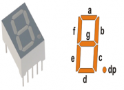
[[File:BasicSevenSegmentDisplay.png|thumbnail|fig 1: Basic 7 segment Display]] | [[File:BasicSevenSegmentDisplay.png|thumbnail|fig 1: Basic 7 segment Display]] | ||
[[File:7 segments Indicator.gif|framed|fig 2: Simulation]] | [[File:7 segments Indicator.gif|framed|fig 2: Simulation]] | ||
| + | Well, the name 7 segments implies there are 7 LED segments arranged as shown in figure 1. | ||
| + | After LEDs they are the easiest interfaces to a microcontroller. | ||
| + | There is also a decimal point or dp. It is used when decimal digits like 5.1 etc are displayed. | ||
| + | ==Applications== | ||
| + | Seven segment are widely used in applications where digits[0-9] are required to be displayed.Although they also display letters A to F as shown in figure(2) simulation. | ||
| + | This is a very simple and convenient way to display numbers in a bright fashion. | ||
| + | ==Form Factor== | ||
| + | |||
| + | *'''Sizes''':They come in various sizes; 0.28”, 0.3”, 0.32”, 0.36”, 0.39”, 0.4”, 0.5”, 0.56”, 0.6”, 0.8”, 1.0”, 1.2”, 1.5”, 1.8”, 2.0”, 2.3”, 3.0”, 4.0”, 5.0”, 7.0”) | ||
| + | *'''Colors''': and varied colors too; Red, Green, Yellow, Orange, Blue, and White. | ||
| + | ==Working== | ||
[[File:Common Cathode 7Segment.jpeg|thumbnail|fig 3:Common Cathode Display]] | [[File:Common Cathode 7Segment.jpeg|thumbnail|fig 3:Common Cathode Display]] | ||
[[File:Common Anode 7Segment.jpeg|thumbnail|fig 4: Common Anode 7 segment]] | [[File:Common Anode 7Segment.jpeg|thumbnail|fig 4: Common Anode 7 segment]] | ||
| + | Since these are basically LEDs arranged as a group they can either have anode in common or cathode. | ||
| + | *'''Common Cathode''': This type of 7 segments, requires a positive voltage(5v) to given to the segments '''a''' to '''g''' in order to glow. This is shown in figure(3). Providing a positive voltage with respect to common cathode makes the LED forward biased. | ||
| + | *'''Common Anode''': This type of 7 segments, requires a negativevoltage(GND) to given to the segments '''a''' to '''g''' in order to glow. This is shown in figure(4). A ground connection to cathode with respect to common anode again forward biases the LED which glows. | ||
}} | }} | ||
Revision as of 11:05, 17 December 2013
Seven Segment Display
Well, the name 7 segments implies there are 7 LED segments arranged as shown in figure 1. After LEDs they are the easiest interfaces to a microcontroller. There is also a decimal point or dp. It is used when decimal digits like 5.1 etc are displayed.
Applications
Seven segment are widely used in applications where digits[0-9] are required to be displayed.Although they also display letters A to F as shown in figure(2) simulation. This is a very simple and convenient way to display numbers in a bright fashion.
Form Factor
- Sizes:They come in various sizes; 0.28”, 0.3”, 0.32”, 0.36”, 0.39”, 0.4”, 0.5”, 0.56”, 0.6”, 0.8”, 1.0”, 1.2”, 1.5”, 1.8”, 2.0”, 2.3”, 3.0”, 4.0”, 5.0”, 7.0”)
- Colors: and varied colors too; Red, Green, Yellow, Orange, Blue, and White.
Working
Since these are basically LEDs arranged as a group they can either have anode in common or cathode.
- Common Cathode: This type of 7 segments, requires a positive voltage(5v) to given to the segments a to g in order to glow. This is shown in figure(3). Providing a positive voltage with respect to common cathode makes the LED forward biased.
- Common Anode: This type of 7 segments, requires a negativevoltage(GND) to given to the segments a to g in order to glow. This is shown in figure(4). A ground connection to cathode with respect to common anode again forward biases the LED which glows.


