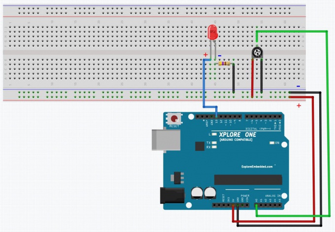
Difference between revisions of "7 Blink LED with POT"
(Created page with "Category:Arduino Tutorials 680px") |
|||
| Line 1: | Line 1: | ||
[[Category:Arduino Tutorials]] | [[Category:Arduino Tutorials]] | ||
[[File:Arduino Blink LED with POT.JPG|680px]] | [[File:Arduino Blink LED with POT.JPG|680px]] | ||
| + | ==Code== | ||
| + | <syntaxhighlight> | ||
| + | /* | ||
| + | Analog Input | ||
| + | Demonstrates analog input by reading an analog sensor on analog pin 0 and | ||
| + | turning on and off a light emitting diode(LED) connected to digital pin 13. | ||
| + | The amount of time the LED will be on and off depends on | ||
| + | the value obtained by analogRead(). | ||
| + | |||
| + | The circuit: | ||
| + | * Potentiometer attached to analog input 0 | ||
| + | * center pin of the potentiometer to the analog pin | ||
| + | * one side pin (either one) to ground | ||
| + | * the other side pin to +5V | ||
| + | * LED anode (long leg) attached to digital output 13 | ||
| + | * LED cathode (short leg) attached to ground | ||
| + | |||
| + | * Note: because most Arduinos have a built-in LED attached | ||
| + | to pin 13 on the board, the LED is optional. | ||
| + | |||
| + | */ | ||
| + | int sensorPin = A0; // select the input pin for the potentiometer | ||
| + | int ledPin = 13; // select the pin for the LED | ||
| + | int sensorValue = 0; // variable to store the value coming from the sensor | ||
| + | void setup() { | ||
| + | // declare the ledPin as an OUTPUT: | ||
| + | pinMode(ledPin, OUTPUT); | ||
| + | } | ||
| + | void loop() { | ||
| + | // read the value from the sensor: | ||
| + | sensorValue = analogRead(sensorPin); | ||
| + | // turn the ledPin on | ||
| + | digitalWrite(ledPin, HIGH); | ||
| + | // stop the program for <sensorValue> milliseconds: | ||
| + | delay(sensorValue); | ||
| + | // turn the ledPin off: | ||
| + | digitalWrite(ledPin, LOW); | ||
| + | // stop the program for for <sensorValue> milliseconds: | ||
| + | delay(sensorValue); | ||
| + | } | ||
| + | <syntaxhighlight> | ||
Revision as of 00:21, 13 September 2014
Code
/*
  Analog Input
 Demonstrates analog input by reading an analog sensor on analog pin 0 and
 turning on and off a light emitting diode(LED)  connected to digital pin 13.
 The amount of time the LED will be on and off depends on
 the value obtained by analogRead().

 The circuit:
 * Potentiometer attached to analog input 0
 * center pin of the potentiometer to the analog pin
 * one side pin (either one) to ground
 * the other side pin to +5V
 * LED anode (long leg) attached to digital output 13
 * LED cathode (short leg) attached to ground

 * Note: because most Arduinos have a built-in LED attached
 to pin 13 on the board, the LED is optional.

 */
int sensorPin = A0;    // select the input pin for the potentiometer
int ledPin = 13;      // select the pin for the LED
int sensorValue = 0;  // variable to store the value coming from the sensor
void setup() {
  // declare the ledPin as an OUTPUT:
  pinMode(ledPin, OUTPUT);
}
void loop() {
  // read the value from the sensor:
  sensorValue = analogRead(sensorPin);
  // turn the ledPin on
  digitalWrite(ledPin, HIGH);
  // stop the program for <sensorValue> milliseconds:
  delay(sensorValue);
  // turn the ledPin off:
  digitalWrite(ledPin, LOW);
  // stop the program for for <sensorValue> milliseconds:
  delay(sensorValue);
}
<syntaxhighlight>

