Difference between revisions of "Dtmf controlled robot using AVR"
| Line 26: | Line 26: | ||
=Schematic In Detail= | =Schematic In Detail= | ||
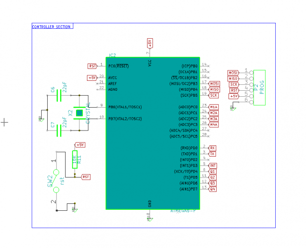
==The Micrcontroller: Atmega8== | ==The Micrcontroller: Atmega8== | ||
| + | [[File:Xplore AVR Robo Controller Section.PNG|thumbnail|x500px|Micrcontroller: Atmega8]] | ||
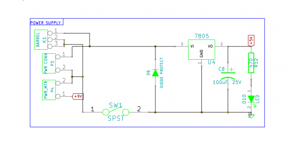
==Power Supply== | ==Power Supply== | ||
| + | [[File:Xplore AVR Robo Power.PNG|thumbnail||x300px|Powersupply: Battery or DC Jack powered]] | ||
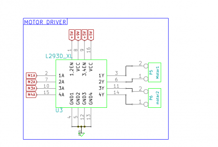
==The Motor Driver L293D== | ==The Motor Driver L293D== | ||
| + | [[File:Xplore AVR Robo Motor Driver.PNG|thumbnail||x300px|Motor Driver L293D]] | ||
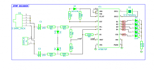
==DTMF Decoder== | ==DTMF Decoder== | ||
| + | [[File:Xplore AVR Robo DTMF Decoder.PNG|thumbnail||x300px|DTMF Decoder using MT8870]] | ||
Revision as of 16:54, 5 February 2014
Contents
Introduction
In this tutorial we will see about building a simple dtmf controlled robot. Whenever we make a call, and press keys, dtmf tones are generated and transmitted. The tones can be easily decoded using a IC like MT8870. This enables a lot of possibilities for wireless control over mobile and telephone. A mobile phone is connected to the robot shield and it can be controlled as shown in the table below
Assembling the Robot Cart
For this we will be using Xplore Robot Chasis as shown. The basic components would be
- Xplore Robo Chasis
- Xplore AVR Robo development board with Integrated DTMF
- Battery Operated [BO] Motors for driving wheels
- Castor as a free wheel.
You could make your own hardware setup as per the schematics discussed in the tutorial. The setup is shown in the pictures below.
...Assembly sequence
<hovergallery maxhoverwidth=600 maxhoverheight=600>
File:Wheel.JPG


