Difference between revisions of "Analog JoyStick with Arduino"
| Line 9: | Line 9: | ||
[[File:0 Joystick with Arduino bb.png|none]] | [[File:0 Joystick with Arduino bb.png|none]] | ||
=Raw Sketch= | =Raw Sketch= | ||
| + | <syntaxhighlight> | ||
| + | #define joyX A0 | ||
| + | #define joyY A1 | ||
| + | |||
| + | void setup() { | ||
| + | Serial.begin(9600); | ||
| + | } | ||
| + | |||
| + | void loop() { | ||
| + | // put your main code here, to run repeatedly: | ||
| + | xValue = analogRead(joyX); | ||
| + | yValue = analogRead(joyY); | ||
| + | |||
| + | //print the values with to plot or view | ||
| + | Serial.print(xValue); | ||
| + | Serial.print("\t"); | ||
| + | Serial.println(yValue); | ||
| + | } | ||
| + | </syntaxhighlight> | ||
| + | |||
=Mapping= | =Mapping= | ||
Revision as of 11:34, 29 July 2016
The Analog Joystick is similar to two potentiometers connected together, one for the vertical movement (Y-axis) and other for the horizontal movement (X-axis). The joystick also comes with a Select switch. It can be very handy for retro gaming, robot control or RC cars. So let's understand how it works!

Contents
Basics
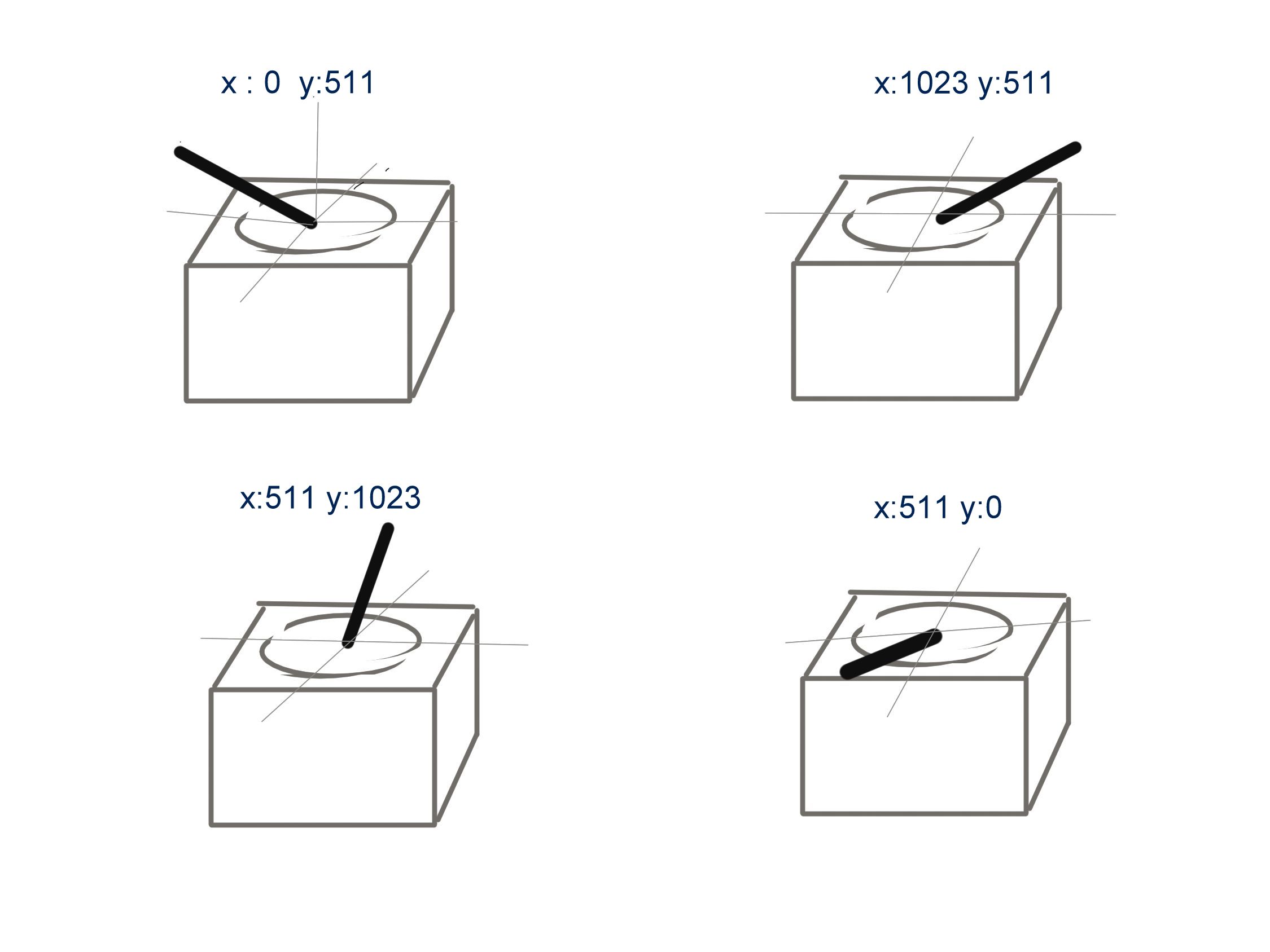
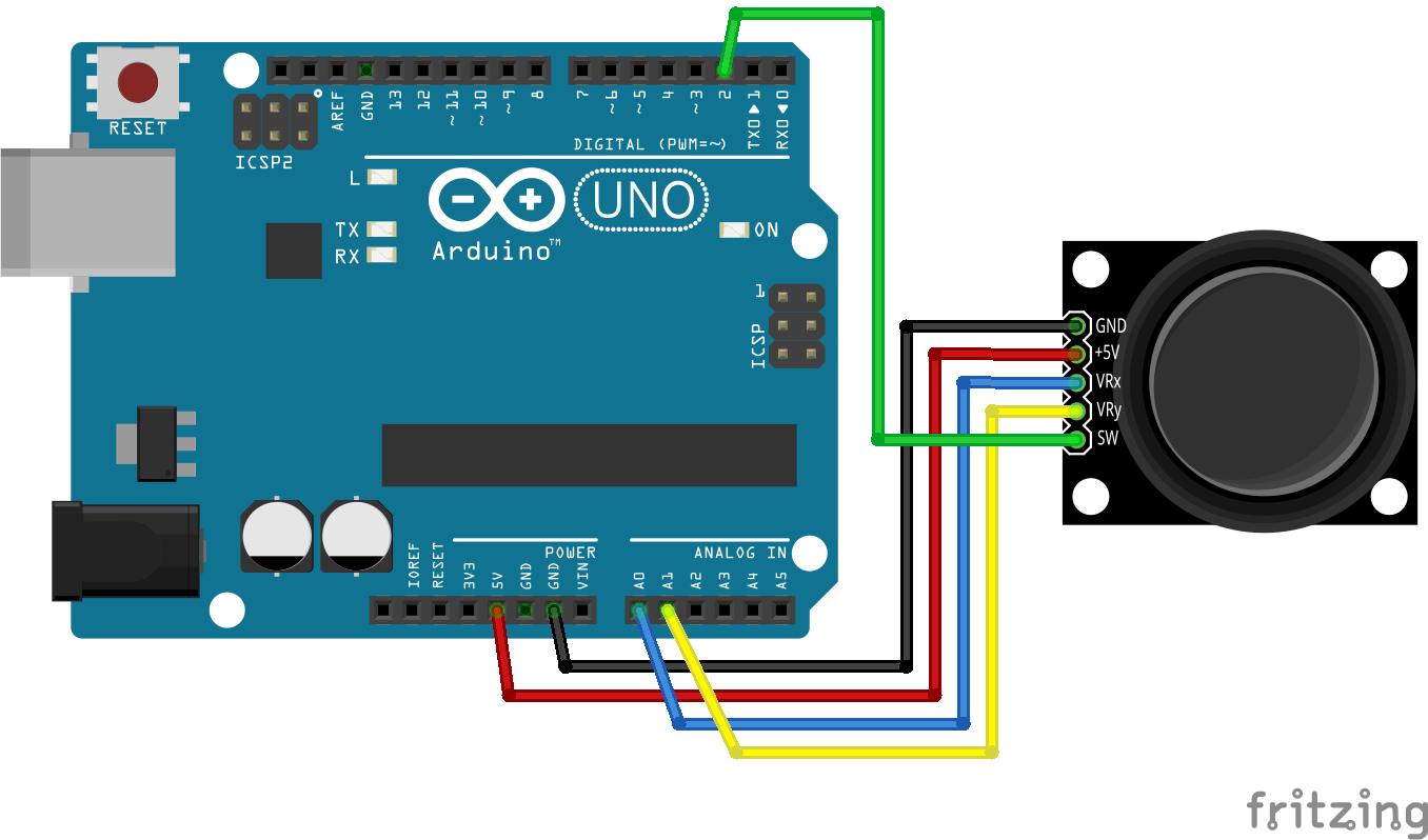
The Arduino Uno or any other Arduino board that uses Atmega328 as the Microcontroller has ADC resolution of 10 bits. Hence the values on each analog channel can vary from 0 to 1023. Now connecting the VRx to A0 and VRy to A1 analog inputs respectively should show values as shown in the image below.
The home position for the stick is at ( x,y:511,511). If the stick is moved on X axis from one end to the other, the X values will change from 0 to 1023 and similar thing happens when moved along the Y axis. On the same lines you can read position of the stick anywhere in upper half hemisphere from combination of these values.
Hookup
Raw Sketch
#define joyX A0
#define joyY A1

void setup() {
  Serial.begin(9600);
}

void loop() {
  // put your main code here, to run repeatedly:
  xValue = analogRead(joyX);
  yValue = analogRead(joyY);

  //print the values with to plot or view
  Serial.print(xValue);
  Serial.print("\t");
  Serial.println(yValue);
}


