Difference between revisions of "Buzzer with PIC16F877A Starter Board"
| Line 4: | Line 4: | ||
=Steps= | =Steps= | ||
| − | #Configure the PORT D0 as output . | + | #Configure the PORT D0 as output to control the buzzer. |
| − | #Configure the PORT D2 as input. | + | #Configure the PORT D2 as input to read the switch status.. |
#Read the switch status. | #Read the switch status. | ||
#ON/OFF the Buzzer as per switch status. | #ON/OFF the Buzzer as per switch status. | ||
Revision as of 18:25, 2 May 2016
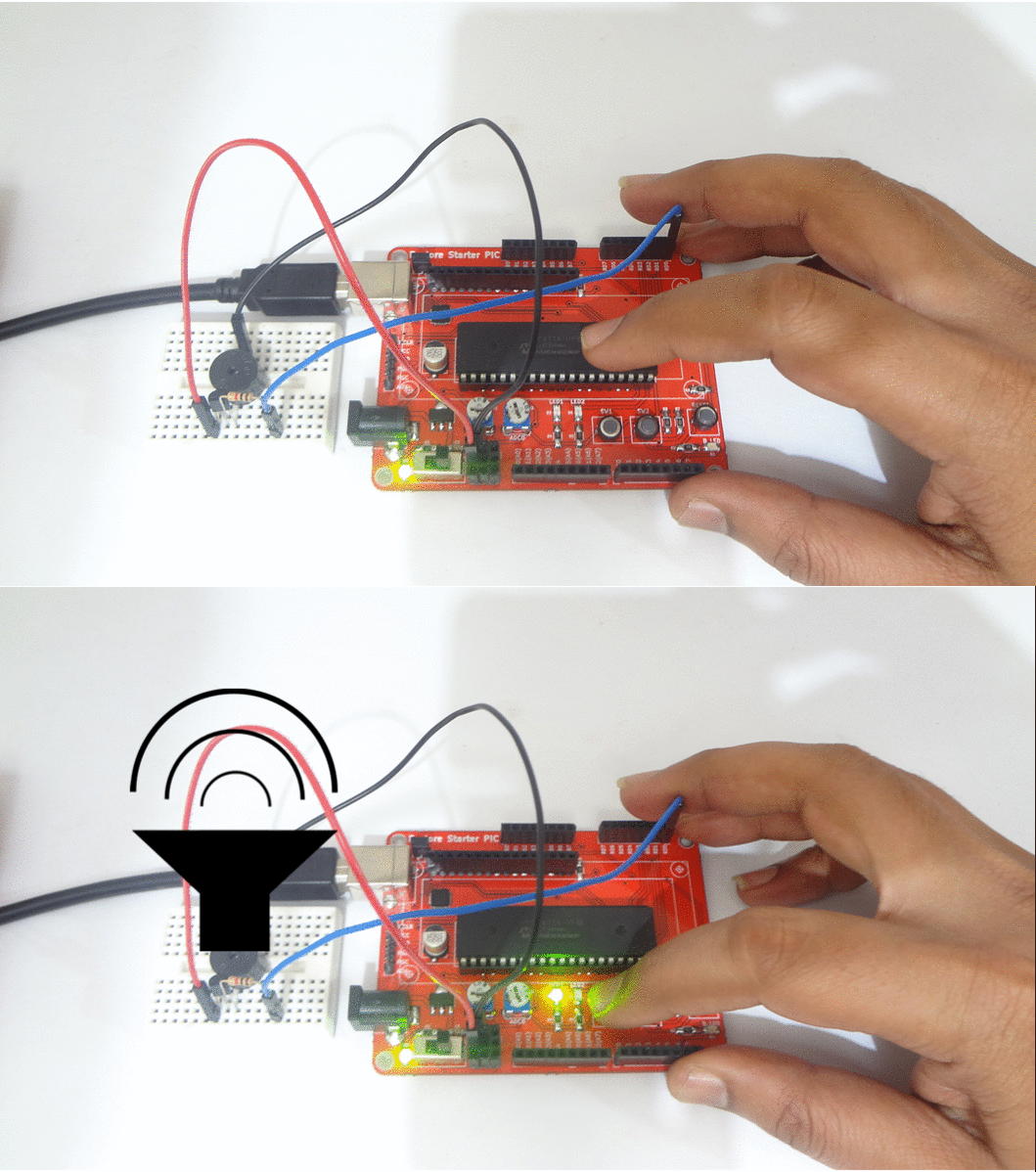
In this tutorial we will see how to interface a switch and buzzer with Pic16f877a starter board.
The switch will be used to control the buzzer.
Steps
- Configure the PORT D0 as output to control the buzzer.
- Configure the PORT D2 as input to read the switch status..
- Read the switch status.
- ON/OFF the Buzzer as per switch status.
Code

