Difference between revisions of "Blinky with Starter AVR"
| Line 3: | Line 3: | ||
=Basic= | =Basic= | ||
On starter AVR board LED's are connected to PD4 and PD5. We are using one connected to PB5 in this example. I am using ''Atmel Studio'' to write the code. | On starter AVR board LED's are connected to PD4 and PD5. We are using one connected to PB5 in this example. I am using ''Atmel Studio'' to write the code. | ||
| − | To know about how to do setting and create a project in | + | To know about how to do setting and create a project in ''Atmel Studio'', look at our [[AVR Hardware and Software Setup]] tutorial. After generating the hex file, look at our [[Setting Up Starter AVR]] tutorial to flash the hex file to the board. |
Revision as of 10:29, 2 April 2016
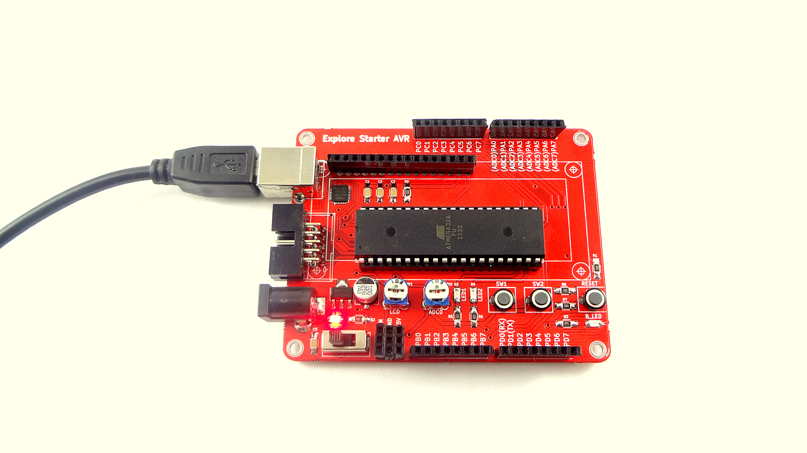
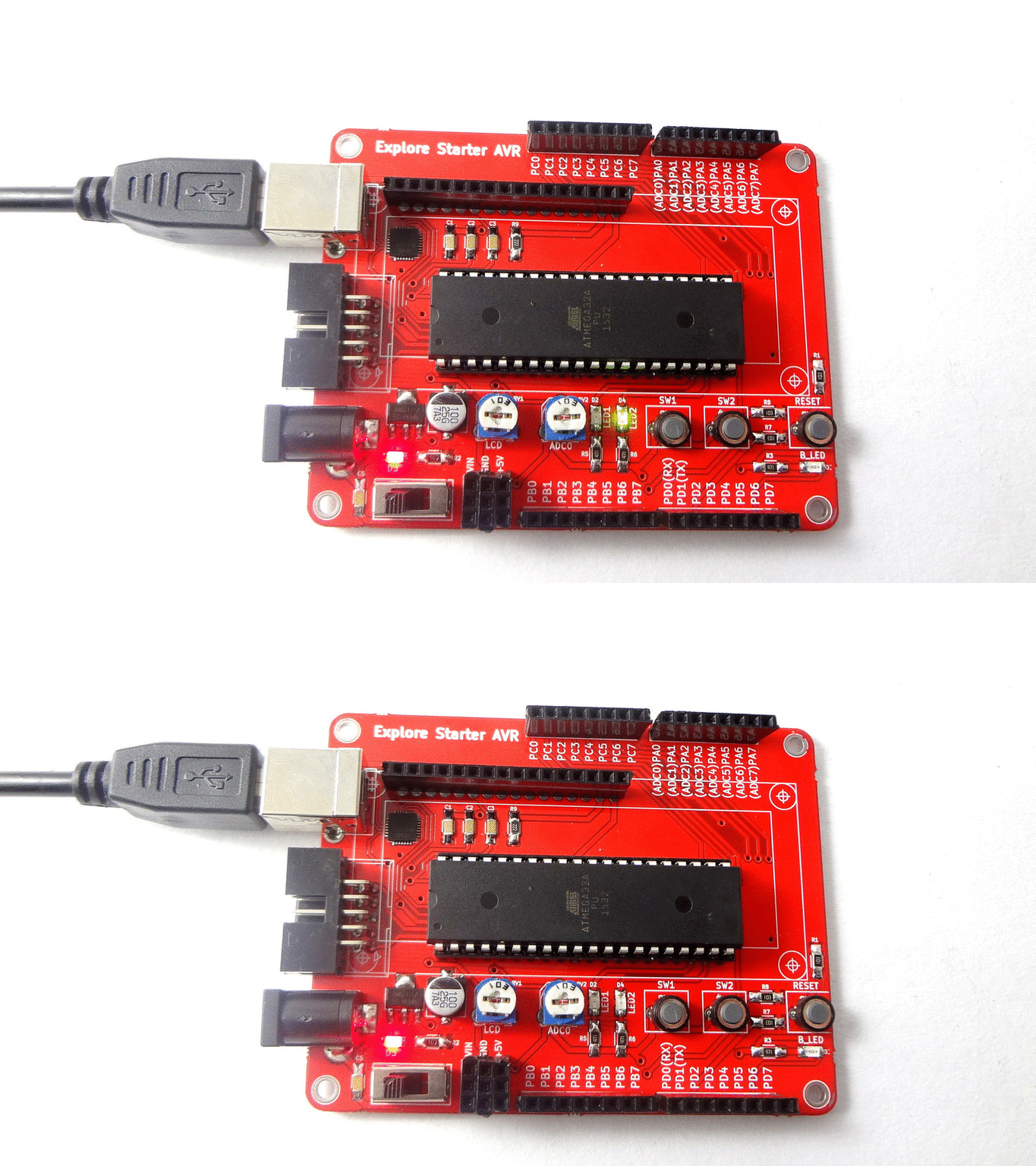
After setting up starter AVR board, we will start with simple LED blinking experiment. Two user LED's are provided on starter AVR board, we will use same for this experiment.
Contents
Basic
On starter AVR board LED's are connected to PD4 and PD5. We are using one connected to PB5 in this example. I am using Atmel Studio to write the code. To know about how to do setting and create a project in Atmel Studio, look at our AVR Hardware and Software Setup tutorial. After generating the hex file, look at our Setting Up Starter AVR tutorial to flash the hex file to the board.


