Difference between revisions of "Interfacing Character LCDs with AVR"
| Line 39: | Line 39: | ||
=LCD 20 x 4= | =LCD 20 x 4= | ||
| − | + | <syntaxhighlight> | |
| + | #include "lcd.h" | ||
| + | int main() | ||
| + | { | ||
| + | /*Connect RS->PB0, RW->PB1, EN->PB2 and data bus to PORTC.4 to PORTC.7*/ | ||
| + | LCD_SetUp(PB_0,PB_1,PB_2,P_NC,P_NC,P_NC,P_NC,PC_4,PC_5,PC_6,PC_7); | ||
| + | LCD_Init(4,20); | ||
| + | |||
| + | LCD_DisplayString("Explore Embedded\n"); | ||
| + | LCD_DisplayString("LCD 4-bit Mode\n"); | ||
| + | LCD_DisplayString("20 x 4 \n"); | ||
| + | LCD_DisplayString(":) :O"); | ||
| + | |||
| + | while(1); | ||
| + | |||
| + | return (0); | ||
| + | } | ||
| + | </syntaxhighlight> | ||
{{#ev:youtube|Z-SD1SaonLE|680}} | {{#ev:youtube|Z-SD1SaonLE|680}} | ||
Revision as of 15:01, 23 March 2016
Contents
Basics
We have covered the basics of character LCDs in the 8051 Tutorial. In this tutorial let's go straight ahead and interface various character display like 16x1, 16x2, 20x4 with AVR atmega32.
Note that most of these displays use a standard display controller like HD44780U, hence a generic code can be written to interface different types mentioned above. Also, these can be interfaced in 4-bit, 8-bit modes.
Hookup
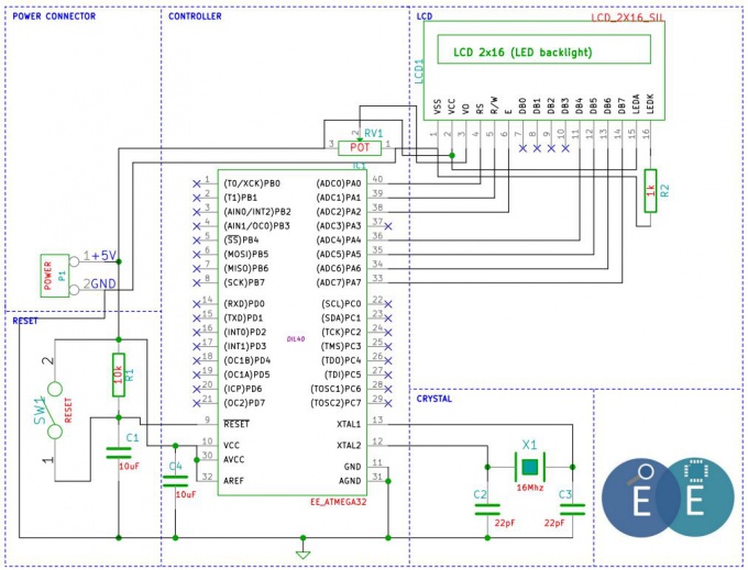
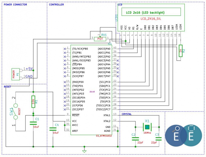
We will connect the display in 4 bit mode as shown in the diagram below. You may change it to 8 bit and make the required connections and corresponding code changes. Also note that the Hardware connections remain same for LCD 16x1, LCD 16x 2 and LCD 20x4 configurations. So let's start with 16x1 LCD.
LCD 16 x 1
#include "lcd.h"
int main()
{
    /*Connect RS->PB0, RW->PB1, EN->PB2 and data bus to PORTC.4 to PORTC.7*/
    LCD_SetUp(PB_0,PB_1,PB_2,P_NC,P_NC,P_NC,P_NC,PC_4,PC_5,PC_6,PC_7);
    LCD_Init(1,16);
    LCD_DisplayString("Explore Embedded");
    while(1);
    return (0);
}
LCD 16 x 2
#include "lcd.h"
int main()
{
    /*Connect RS->PB0, RW->PB1, EN->PB2 and data bus to PORTC.4 to PORTC.7*/
    LCD_SetUp(PB_0,PB_1,PB_2,P_NC,P_NC,P_NC,P_NC,PC_4,PC_5,PC_6,PC_7);
    LCD_Init(2,16);

    LCD_DisplayString("Explore Embedded");
    LCD_DisplayString("Lcd 4-bit Mode");
    while(1);

    return (0);
}
LCD 20 x 4
#include "lcd.h"
int main()
{
    /*Connect RS->PB0, RW->PB1, EN->PB2 and data bus to PORTC.4 to PORTC.7*/
    LCD_SetUp(PB_0,PB_1,PB_2,P_NC,P_NC,P_NC,P_NC,PC_4,PC_5,PC_6,PC_7);
    LCD_Init(4,20);

    LCD_DisplayString("Explore Embedded\n");
    LCD_DisplayString("LCD 4-bit Mode\n");
    LCD_DisplayString("20 x 4 \n");
    LCD_DisplayString(":)  :O");

    while(1);

    return (0);
}
Code and Explanation will be ubdated soon..


