Difference between revisions of "6.8051 Interrupts"
| Line 5: | Line 5: | ||
In other words the microcontroller, need not monitor the timers, the serial communication or the external pins P3.2 and P3.3. Whenever an event related to these units occur, it is informed to microcontroller with the help of interrupts. | In other words the microcontroller, need not monitor the timers, the serial communication or the external pins P3.2 and P3.3. Whenever an event related to these units occur, it is informed to microcontroller with the help of interrupts. | ||
=Basics= | =Basics= | ||
| + | ==Interrupt sources for 8051== | ||
For the 8051 Microcontroller there are six interrupt sources as shown in the table below: | For the 8051 Microcontroller there are six interrupt sources as shown in the table below: | ||
}} | }} | ||
| Line 23: | Line 24: | ||
|- | |- | ||
|Serial Com Interrupt(RI and TI)||0023||-||Program SW | |Serial Com Interrupt(RI and TI)||0023||-||Program SW | ||
| + | |} | ||
| + | {{Box|type=l_green_light|text=As seen in the above table, | ||
| + | *the reset vector has just 3 bytes allocated to it, meaning it can hold a jump instruction to the location where the main program is stored. | ||
| + | *The other interrupts have 8 bytes allocated to each of them, hence a small Interrupt service routine(ISR) can be placed here. However, if the ISR needs to larger in length, it has to placed else where and the allocated 8 bytes need to have the code that simple redirects the control to the ISR. | ||
| + | *''INT0'' and ''INT1'' are external interrupts on P3.2 and P3.3 respectively. These can be configured to be low level triggered or edge triggered interrupt sources. | ||
| + | *''TF0'' and ''TF1'' are timer overflow interrupts for timer 0 and 1 respectively | ||
| + | *The ''Serial COM Interrupt'' can be configured to trigger upon transmit or receipt of a byte during serial communication. | ||
| + | ==Enabling and Disabling the Interrupts== | ||
| + | It should be noted that when the MCU is reset, all the interrupts are disabled. Hence in order to use them, we should enable them. | ||
| + | In 8051 '''Interrupt Enable(EA)''' Register is used to enable or disable the interrupt. The register is shown below: | ||
| + | }} | ||
| + | {| class="wikitable" style="text-align:center;background-color:#87A96B;" | ||
| + | |- | ||
| + | !colspan = '8'|EA | ||
| + | |- | ||
| + | |D7||D6||D5||D4||D3||D2||D1||D0 | ||
| + | |- | ||
| + | |EA||-||ET2||ES||ET1||EX1||ET0||EX0 | ||
|} | |} | ||
Revision as of 15:00, 1 August 2014
Intro
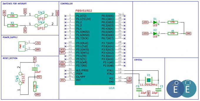
In this tutorial we will look at 8051 Interrupts. Interrupts are useful in many cases wherein the process simply wants to continue doing it's main job and other units(timers or external events) seek its attention when required. In other words the microcontroller, need not monitor the timers, the serial communication or the external pins P3.2 and P3.3. Whenever an event related to these units occur, it is informed to microcontroller with the help of interrupts.
Basics
Interrupt sources for 8051
For the 8051 Microcontroller there are six interrupt sources as shown in the table below:
| Interrupt | ROM Location(Hex) | Pin | Flag Clearing |
|---|---|---|---|
| Reset | 0000 | 9 | Auto |
| External HW Interrupt 0 (INT0) | 0003 | P3.2(12) | Auto |
| Timer 0 Interrupt(TF0) | 000B | - | Auto |
| External HW Interrupt 1 (INT1) | 0013 | P3.3(13) | Auto |
| Timer 1 Interrupt(TF1) | 001B | - | Auto |
| Serial Com Interrupt(RI and TI) | 0023 | - | Program SW |
- the reset vector has just 3 bytes allocated to it, meaning it can hold a jump instruction to the location where the main program is stored.
- The other interrupts have 8 bytes allocated to each of them, hence a small Interrupt service routine(ISR) can be placed here. However, if the ISR needs to larger in length, it has to placed else where and the allocated 8 bytes need to have the code that simple redirects the control to the ISR.
- INT0 and INT1 are external interrupts on P3.2 and P3.3 respectively. These can be configured to be low level triggered or edge triggered interrupt sources.
- TF0 and TF1 are timer overflow interrupts for timer 0 and 1 respectively
- The Serial COM Interrupt can be configured to trigger upon transmit or receipt of a byte during serial communication.
Enabling and Disabling the Interrupts
It should be noted that when the MCU is reset, all the interrupts are disabled. Hence in order to use them, we should enable them. In 8051 Interrupt Enable(EA) Register is used to enable or disable the interrupt. The register is shown below:
| EA | |||||||
|---|---|---|---|---|---|---|---|
| D7 | D6 | D5 | D4 | D3 | D2 | D1 | D0 |
| EA | - | ET2 | ES | ET1 | EX1 | ET0 | EX0 |

