Difference between revisions of "5.8051 Timer programming"
| Line 64: | Line 64: | ||
*<b>Gate Control</b> | *<b>Gate Control</b> | ||
0 = Timer enabled<br> | 0 = Timer enabled<br> | ||
| − | 1 = Timer enabled if INTx | + | 1 = Timer enabled if INTx is high |
*<b>C/T:</b>Counter or Timer Selector | *<b>C/T:</b>Counter or Timer Selector | ||
0 = Internal count source (clock/12)<br> | 0 = Internal count source (clock/12)<br> | ||
Revision as of 12:39, 22 August 2016
In this tutorial, we are going to discuss the Timer module of 8051.
First, we will see what are timers, their working and later we will configure the 8051 timers to generate the delay of 100ms and 500ms respectively. At the end, we will see how to use the ExploreEmdedded Timer library.
Contents
8051 Timer Module
8051 has two indepenndent timer which can be used as timer(to generate delays)/Counters(count external events).
Timer 1 is also used for generating baud rate in serial communication, which we will discuss in the next tutorial
Below table provides the details of the 8051 Timers.
| Timer | Size | Control Register | Count Register | Min Delay | Max Delay |
|---|---|---|---|---|---|
| TIMER0 | 16-bit | TMOD,TCON | TH0,TL0 | 0.2usec | 13.107ms |
| TIMER1 | 16-bit | TMOD,TCON | TH1,TL1 | 0.2usec | 104.857ms |
| TIMER2(8052 only) | 16-bit | TMOD,TCON | TH1,TL1 | 0.2usec | 104.857ms |
Timer Calculation
8051 Oscillator frequency is divided by 12 and then fed to the controller,
Time to increment the Timer count by one(timer tick) can be determined as below.
tick = (1/(Fosc/12)
$$tick = 12/Fosc$$
For Fosc == 11.0592Mhz, the tick time will be
tick = 12/11.0592M = 1.085069444us = 1.085us
Now the Timer value for the required delay can be calculated as below.
Delay = TimerCount * tick
Count = (Delay/tick)
RegValue = TimerMax- Count
RegValue = TimerMax-(Delay/tick) = TimerMax - (Delay/1.085us)
$$RegValue = TimerMax-((Delay/1.085) * 10^6)$$
Timer Basics
As the name suggests these are used to measure the time or generate the accurate time delay. The microcontroller can also generate/measure the required time delays by running loops, but the timer/counter relieves the CPU from that redundant and repetitive task, allowing it to allocate maximum processing time for other tasks.
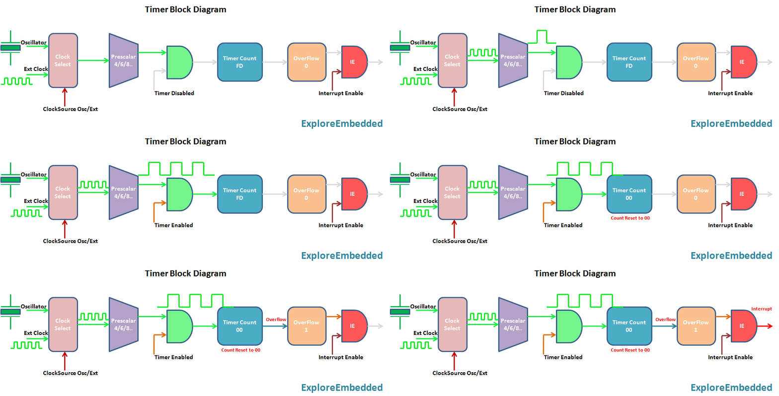
The timer is nothing but a simple binary counter that can be configured to count clock pulses(Internal/External). Once it reaches the Max value, it will roll back to zero setting up an OverFlow flag and generates the interrupt if enabled.

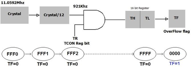
The Timer 0 is 16 bit wide as shown. This can be accessed as 2 eight bit registers TL0 and TL1. Same applies to Timer 1. The 8051 timer and counter are the same units, but in this tutorial, we will discuss only the timer unit to simplify the discussion. Fig 1, shows the basic 8051 timer unit. The registers TCON and TMOD affect the timer operation. The clock frequency is divided by 12 and used by the timer unit. Thus if a 11.0592MHz external crystal is used, the timer uses a frequency of 921KHz. Thus timer increments every (1/921Khz) = 1.085μ seconds.
- The C/Ṫ = 0 bit of TMOD register selects operation of Timer/counter unit as timer.
- The TR bit of TCON register is used to start the timer.
Timer Registers
| TMOD | |||||||
| Timer1 | Timer 0 | ||||||
|---|---|---|---|---|---|---|---|
| 7 | 6 | 5 | 4 | 3 | 2 | 1 | 0 |
| Gate | C/T | M1 | M0 | Gate | C/T | M1 | M0 |
- Gate Control
0 = Timer enabled
1 = Timer enabled if INTx is high
- C/T:Counter or Timer Selector
0 = Internal count source (clock/12)
1 = External count source T0/T1(P3.4/P3.5) pin.
- M1-M0:Mode Control
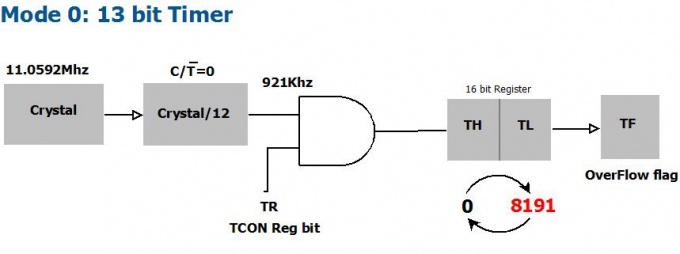
00-Mode 0, 13 bit count mode
01-Mode 1, 16 bit count mode
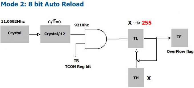
10-Mode 2, Auto reload mode
11-Mode 3, Split Timer mode
TCON Register
| TCON | |||||||
|---|---|---|---|---|---|---|---|
| D7 | D6 | D5 | D4 | D3 | D2 | D1 | D0 |
| TF1 | TR1 | TF0 | TR0 | IE1 | IT1 | IE0 | IT0 |
| Timer1 | Timer 0 | Interrupts | |||||
Timer Example
#include<reg51.h>
void delay_t0(void);// function prototype

void delay_t0()
{
   TMOD = 0x01; //Timer zero mode 1
   TH0 = 0X4B;
   TL0 = 0XFF;
   TR0 = 1; //turn ON Timer zero
   while(TF0 == 0);
   TF0 = 0; //clear the timer
   TR0 = 0;
}
void main()
{
  P3 = 0x00; //set port as output
  while(1)
  {
   P3 = 0XFF;
   delay_t0();
   P3 = 0X00;
   delay_t0();
  }
}
{{#seo: |title=8051_Timers |titlemode=append |keywords=8051,AT89s51,at89c51,p89v51rd2,XploreLabz,Timer,Timers,8051 timers/counters,8051 timer operation,8051 Timer registers,TMOD Register,TCON register |description=8051 Timers }} Would like to have your feedback and suggestions here;


