Difference between revisions of "NEC IR Remote Control Interface with 8051"
| (One intermediate revision by the same user not shown) | |||
| Line 1: | Line 1: | ||
[[Category:8051 tutorials]] | [[Category:8051 tutorials]] | ||
| + | [[Category:IR Remote]] | ||
IR Remote Controllers and receivers follow standard protocols for sending and receiving the data. Some of the standard protocols are NEC , JVC , SIRC (Sony Infrared Remote Control) etc. | IR Remote Controllers and receivers follow standard protocols for sending and receiving the data. Some of the standard protocols are NEC , JVC , SIRC (Sony Infrared Remote Control) etc. | ||
We will be discussing only the NEC protocol. After understanding the frame format of IR Remote, We will be interfacing a IR receiver with 8051 and decode the key pressed. | We will be discussing only the NEC protocol. After understanding the frame format of IR Remote, We will be interfacing a IR receiver with 8051 and decode the key pressed. | ||
| Line 99: | Line 100: | ||
=Downloads= | =Downloads= | ||
| + | Download the complete project folder from this link: [https://github.com/ExploreEmbedded/8051_DevelopmentBoard Examples and Code Library]<br> | ||
| + | |||
Have an opinion, suggestion , question or feedback about the article let it out here! | Have an opinion, suggestion , question or feedback about the article let it out here! | ||
{{DISQUS}} | {{DISQUS}} | ||
Latest revision as of 17:19, 26 August 2016
IR Remote Controllers and receivers follow standard protocols for sending and receiving the data. Some of the standard protocols are NEC , JVC , SIRC (Sony Infrared Remote Control) etc. We will be discussing only the NEC protocol. After understanding the frame format of IR Remote, We will be interfacing a IR receiver with 8051 and decode the key pressed.
NEC Protocol
NEC IR protocol encodes the keys using a 32bit frame format as shown below.
| NEC Frame Format | |||
| Address | Complement of Address | Command | Complement of Command |
| LSB-MSB(0-7) | LSB-MSB(8-15) | LSB-MSB(16-23) | LSB-MSB(24-31) |
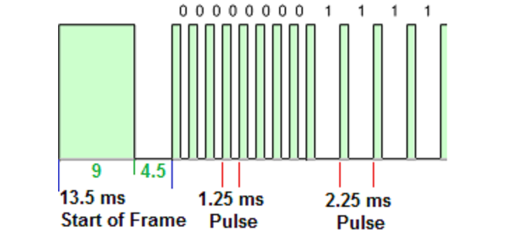
Each bit is transmitted using the pulse distance as shown in the image.
Logical '0': A 562.5µs pulse burst followed by a 562.5µs space, with a total transmit time of 1.125ms
Logical '0': A 562.5µs pulse burst followed by a 1.6875ms space, with a total transmit time of 2.25ms

When a key is pressed on the remote controller, the message transmitted consists of the following, in order:
- A 9ms leading pulse burst (16 times the pulse burst length used for a logical data bit)
- A 4.5ms space
- The 8-bit address for the receiving device
- The 8-bit logical inverse of the address
- The 8-bit command
- The 8-bit logical inverse of the command
- A final 562.5µs pulse burst to signify the end of message transmission.
The four bytes of data bits are each sent least significant bit first. Below image illustrates the format of an NEC IR transmission frame, for an address of 00h (00000000b) and a command of ADh (10101101b).
A total of 67.5ms is required to transmit a message frame. It needs 27ms to transmit the 16 bits of address (address + inverse) and the 16 bits of command (command + inverse).

IR Key Codes
Below table gives the complete list of Codes for NEC IR Remote.
| Key | Encoded Value |
| CH- | 0xFFA25D |
| CH | 0xFF629D |
| CH+ | 0xFFE21D |
| PREV | 0xFF22DD |
| NEXT | 0xFF02FD |
| PLAY/PAUSE | 0xFFC23D |
| VOL- | 0xFFE01F |
| VOL+ | 0xFFA857 |
| EQ | 0xFF906F |
| 0 | 0xFF6897 |
| 100+ | 0xFF9867 |
| 200+ | 0xFFB04F |
| 1 | 0xFF30CF |
| 2 | 0xFF18E7 |
| 3 | 0xFF7A85 |
| 4 | 0xFF10EF |
| 5 | 0xFF38C7 |
| 6 | 0xFF5AA5 |
| 7 | 0xFF42BD |
| 8 | 0xFF4AB5 |
| 9 | 0xFF52AD |
Sample Code
Below is the sample code to decode the key pressed on IR remote control and send on UART. We need an External interrupt to detect the pulses and timer to measure these pulse widths.
- INT0(P2.2) will be configured as falling Edge interrupt to detect the pulses.
- Timer0(Mode1) will be configured to generate a periodic interrupt of 1ms.
First two transitions will be ignored as they will mark SOF(Start of the frame). After this continuously 32-bit information will be captured in a variable. If the pulse width is greater than 2ms then it will be considered as LOGIC-1 else as LOGIC-0. If the pulse width is greater than 50ms then it will be considered as SOF(Start of the frame).
1ms Delay Calculation:
- Clock Freq=11.0592 Mhz
- Machine Cycle = 12
- Delay=1ms
$$TimerValue= 65536 - ((Delay * ClockFreq)/Machine Cycle)=65536-((1ms * 11.0592Mhz)/12) = 65536 - 921= 0xFC67$$
Using IR Remote Library
Downloads
Download the complete project folder from this link: Examples and Code Library
Have an opinion, suggestion , question or feedback about the article let it out here!
