Difference between revisions of "PWM on Explore M3"
| (One intermediate revision by the same user not shown) | |||
| Line 5: | Line 5: | ||
=Prerequisites= | =Prerequisites= | ||
| − | Please check [[LPC1768: | + | Please check [[LPC1768: PWM|this tutorial]] for detailed explanation on Lpc1768 PWM module.<br> |
If you are doing it for the first time, then check the below links to setup the project for generating the .bin file. | If you are doing it for the first time, then check the below links to setup the project for generating the .bin file. | ||
#[[LPC1768: Keil Project For Bin File|Keil4 Setup]] | #[[LPC1768: Keil Project For Bin File|Keil4 Setup]] | ||
| Line 34: | Line 34: | ||
=Code= | =Code= | ||
| + | Below is the example to vary the brightness of the LED using PWM.<br> | ||
| + | <html> | ||
| + | <script src="https://gist.github.com/SaheblalBagwan/33b205b473f762c9bfa992921f8e2554.js"></script> | ||
| + | </html> | ||
Latest revision as of 14:35, 29 April 2016
In this tutorial we will see how to generate the PWM signals on Explore M3.
Prerequisites
Please check this tutorial for detailed explanation on Lpc1768 PWM module.
If you are doing it for the first time, then check the below links to setup the project for generating the .bin file.
Explore M3 PWM Module
Explore M3 has 6 PWM output pins(24-29) which are mapped to internal PWM module as shown below.
| Explore M3 Pin | LPC1768 Pin | PWM Channel |
|---|---|---|
| 29 | P2.0 | PWM1[1] |
| 28 | P2.1 | PWM1[2] |
| 27 | P2.2 | PWM1[3] |
| 26 | P2.3 | PWM1[4] |
| 25 | P2.4 | PWM1[5] |
| 24 | P2.5 | PWM1[6] |
Code
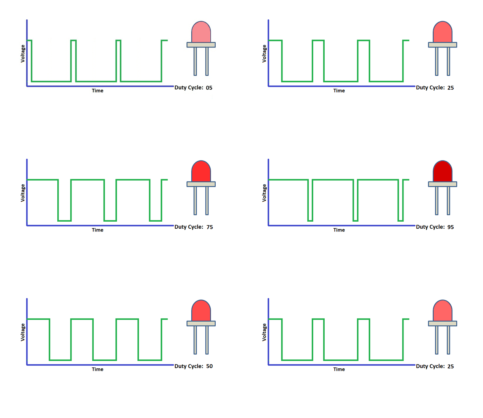
Below is the example to vary the brightness of the LED using PWM.

