Difference between revisions of "Lcd 4-bit with Explore M3"
| (2 intermediate revisions by one other user not shown) | |||
| Line 25: | Line 25: | ||
=Code= | =Code= | ||
| − | Below is the sample code the | + | ==LCD 1x16== |
| + | Below is the sample code for 1x16 Lcd in 4-bit mode. | ||
| + | <html> | ||
| + | <script src="https://gist.github.com/SaheblalBagwan/967bbafb650bfde8e5fba635f0b8079f.js"></script> | ||
| + | </html> | ||
| + | <br><br> | ||
| + | |||
| + | ==LCD 2x16== | ||
| + | Below is the sample code for 2x16 Lcd in 4-bit mode. | ||
<html> | <html> | ||
<script src="https://gist.github.com/SaheblalBagwan/14a9ac0419c28bca2eddf8ffb6b682e4.js"></script> | <script src="https://gist.github.com/SaheblalBagwan/14a9ac0419c28bca2eddf8ffb6b682e4.js"></script> | ||
| Line 31: | Line 39: | ||
<br><br> | <br><br> | ||
| + | ==LCD 4x20== | ||
| + | Below is the sample code for 4x20 Lcd in 4-bit mode. | ||
| + | <html> | ||
| + | <script src="https://gist.github.com/SaheblalBagwan/740289fa59181353b2092ddd74e2d2fa.js"></script> | ||
| + | </html> | ||
| + | <br><br> | ||
| + | [[File:01LCD 4bit.png ]] | ||
=Demo= | =Demo= | ||
Latest revision as of 11:25, 5 May 2016
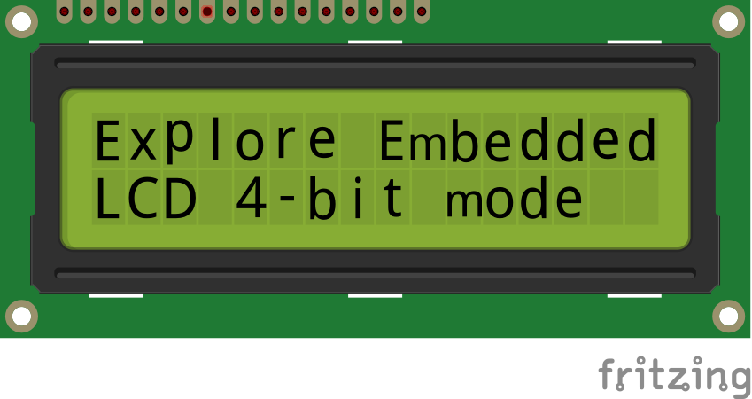
In this tutorial we will see how to interface lcd in 4-bit mode using the explore Embedded bare metal libraries.
At the end will see how to use the libraries for 1x16, 2x16 and 4x20 LCD's.
The libraries can be used on different platforms like Keil, ARM GCC, GCC And Eclipse etc.
Prerequisites
Please check this tutorial for detailed explanation on LCD.
If you are doing it for the first time, then check the below links to setup the project for generating the .bin file.
Hardware Connection
| RS | RW | EN | D0 | D1 | D2 | D3 | D4 | D5 | D6 | D7 |
|---|---|---|---|---|---|---|---|---|---|---|
| 5 | 6 | 7 | P_NC | P_NC | P_NC | P_NC | 12 | 13 | 14 | 15 |
- P_NC: Pin Not Connected
Code
LCD 1x16
Below is the sample code for 1x16 Lcd in 4-bit mode.
LCD 2x16
Below is the sample code for 2x16 Lcd in 4-bit mode.
LCD 4x20
Below is the sample code for 4x20 Lcd in 4-bit mode.

