Difference between revisions of "Switch and a LED with Atmega128 Breakout"
Raghavendra (Talk | contribs) (Created page with "category:Atmega128 Breakout Now we will control the LED depending on external input. In this tutorial we will interface a switch to one of the port pin and display its sta...") |
Raghavendra (Talk | contribs) |
||
| (2 intermediate revisions by the same user not shown) | |||
| Line 2: | Line 2: | ||
Now we will control the LED depending on external input. In this tutorial we will interface a switch to one of the port pin and display its status on LED connected to other port. | Now we will control the LED depending on external input. In this tutorial we will interface a switch to one of the port pin and display its status on LED connected to other port. | ||
=Basics= | =Basics= | ||
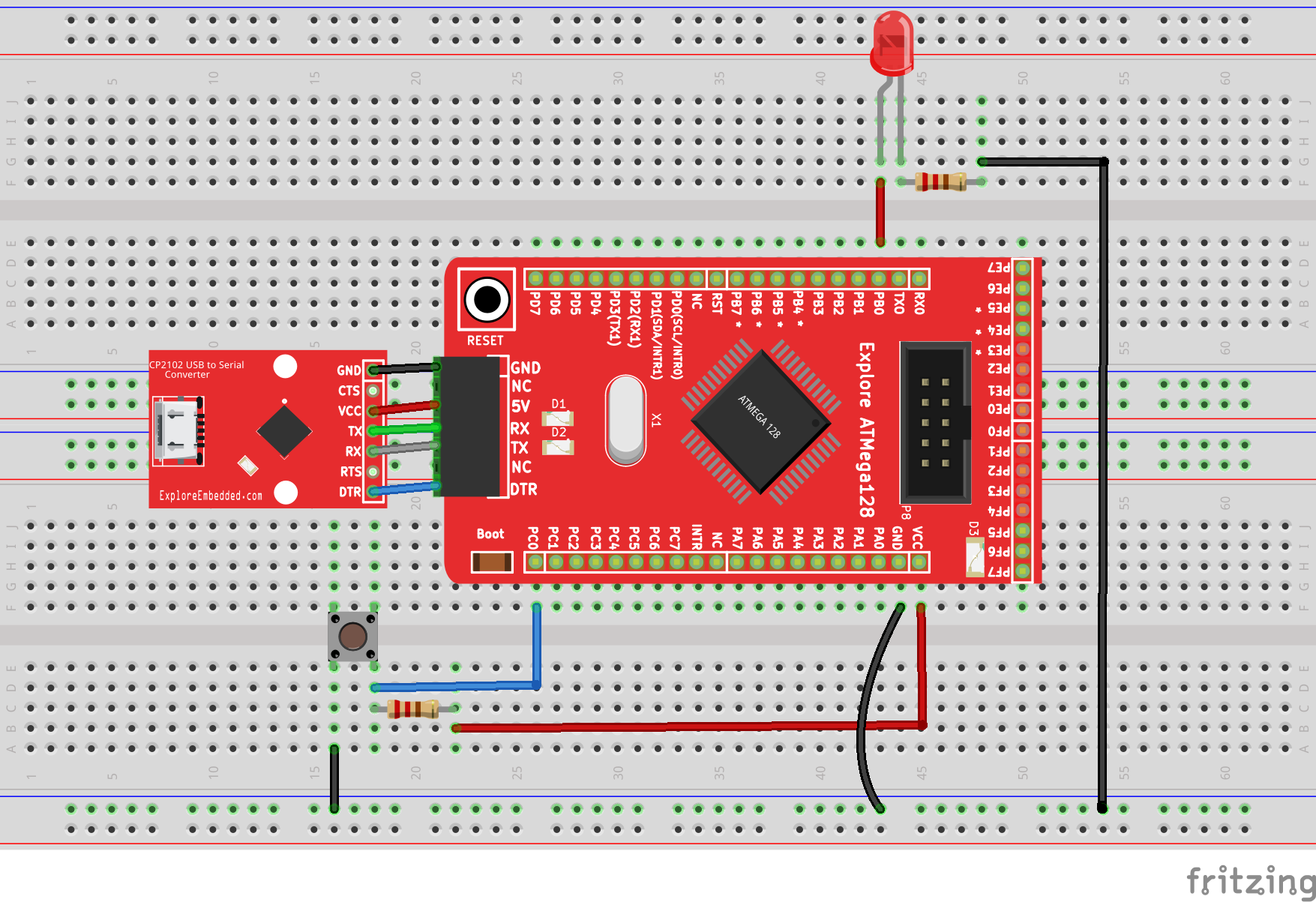
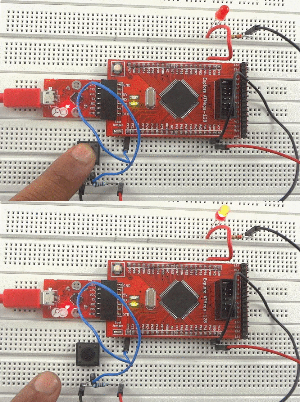
| − | For this tutorial we will a connect a switch to PORT C0 and LED to PORT B0 of | + | For this tutorial we will a connect a switch to PORT C0 and LED to PORT B0 of Atmega128. W will configure PORT A0 as input to read the switch status and PORT C0 as outputto display the switch status on LED. Initially LED will be ON , when we press switch the LED will be OFF. |
<br/> | <br/> | ||
Refer the [[AVR I/O Register Configuration]] tutorial for basics of GPIO register configuration. | Refer the [[AVR I/O Register Configuration]] tutorial for basics of GPIO register configuration. | ||
| Line 15: | Line 15: | ||
=Demo= | =Demo= | ||
| − | [[ | + | [[File:0Switch and a LED with Atmega128 Breakout.gif|none]] |
| − | =Downloads= | + | =Video Tutorial= |
| + | For those of you, who would like to watch instead of read we have made a video with all the gyan. | ||
| + | <br> | ||
| + | {{#ev:youtubehd|-lNAmSNV2-Q|640}} | ||
| + | |||
| + | |||
| + | = Downloads= | ||
| + | Download the complete project folder from the below link: | ||
| + | https://github.com/ExploreEmbedded/ATMega-128-Break-Out-BoardDVB-12007/archive/master.zip<br> | ||
| + | |||
| + | |||
| + | |||
| + | Have a opinion, suggestion , question or feedback about the article let it out here! | ||
| + | {{DISQUS}} | ||
Latest revision as of 12:28, 19 April 2016
Now we will control the LED depending on external input. In this tutorial we will interface a switch to one of the port pin and display its status on LED connected to other port.
Contents
Basics
For this tutorial we will a connect a switch to PORT C0 and LED to PORT B0 of Atmega128. W will configure PORT A0 as input to read the switch status and PORT C0 as outputto display the switch status on LED. Initially LED will be ON , when we press switch the LED will be OFF.
Refer the AVR I/O Register Configuration tutorial for basics of GPIO register configuration.
Hook Up
Code
Demo
Video Tutorial
For those of you, who would like to watch instead of read we have made a video with all the gyan.
Downloads
Download the complete project folder from the below link:
https://github.com/ExploreEmbedded/ATMega-128-Break-Out-BoardDVB-12007/archive/master.zip
Have a opinion, suggestion , question or feedback about the article let it out here!


