Difference between revisions of "Blinky with Atmega128 Breakout"
Raghavendra (Talk | contribs) (Created page with "category:Atmega128 Breakout In this tutorial we will get hands on with Atmega128 breakout board. Here we will interface simple LED with one of the port pins. For this tuto...") |
Raghavendra (Talk | contribs) |
||
| (One intermediate revision by the same user not shown) | |||
| Line 16: | Line 16: | ||
=Demo= | =Demo= | ||
| − | [[none]] | + | [[File:0Blinky with Atmega128 Breakout.gif|none]] |
| − | =Downloads= | + | |
| + | =Video Tutorial= | ||
| + | For those of you, who would like to watch instead of read we have made a video with all the gyan. | ||
| + | <br> | ||
| + | {{#ev:youtubehd|-lNAmSNV2-Q|640}} | ||
| + | |||
| + | |||
| + | = Downloads= | ||
| + | Download the complete project folder from the below link: | ||
| + | https://github.com/ExploreEmbedded/ATMega-128-Break-Out-BoardDVB-12007/archive/master.zip<br> | ||
| + | |||
| + | |||
| + | |||
| + | Have a opinion, suggestion , question or feedback about the article let it out here! | ||
| + | {{DISQUS}} | ||
Latest revision as of 12:23, 19 April 2016
In this tutorial we will get hands on with Atmega128 breakout board. Here we will interface simple LED with one of the port pins. For this tutorial we will require a breadboard, LED and resistor.
Contents
Basics
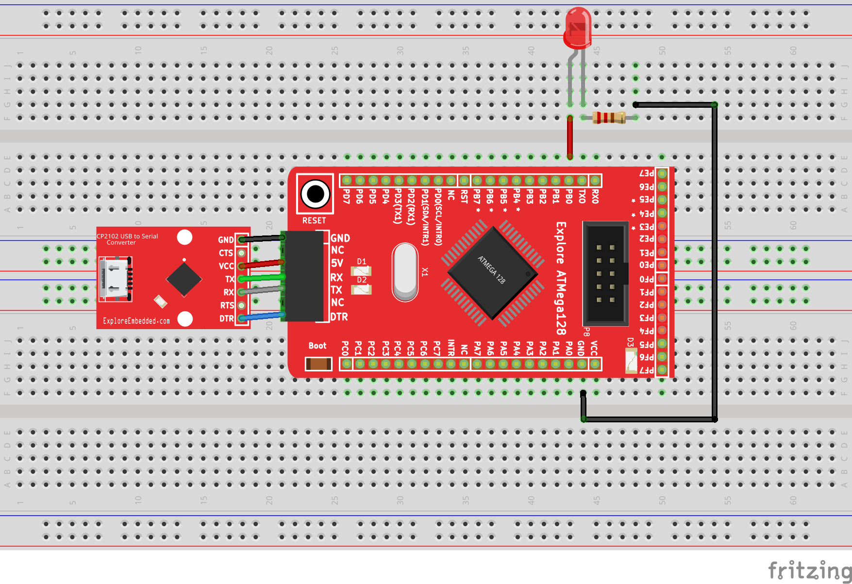
All the port pins of the Atmega128 are taken out on breakout board so that you can easily interface any peripheral with it. We will connect the LED to PORT B0 as shown below.Usually 220,470 or 1k ohm resistor is used as a current limiting resistor to prevent the LED from blowing up.
Refer the AVR I/O Register Configuration tutorial for basics of GPIO register configuration.
Hook up
Code
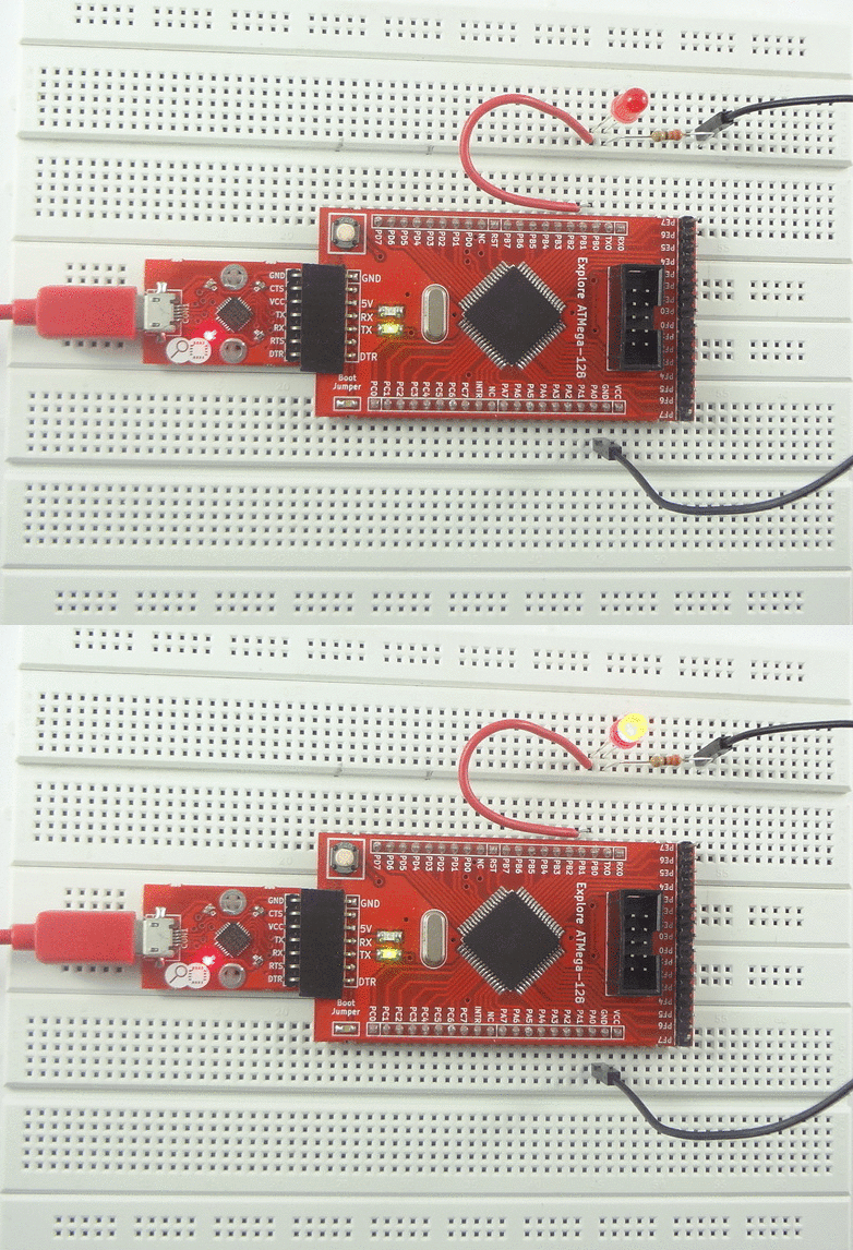
Demo
Video Tutorial
For those of you, who would like to watch instead of read we have made a video with all the gyan.
Downloads
Download the complete project folder from the below link:
https://github.com/ExploreEmbedded/ATMega-128-Break-Out-BoardDVB-12007/archive/master.zip
Have a opinion, suggestion , question or feedback about the article let it out here!


