Difference between revisions of "Reading Temperature with AVR ADC"
Raghavendra (Talk | contribs) |
|||
| (11 intermediate revisions by 2 users not shown) | |||
| Line 2: | Line 2: | ||
The Atmega32 comes with a 10-bit, 8 channel inbuilt Ananlog to Digital Convertor (ADC). We will set it up and read temperature from LM35 and light with a simple (light dependent Resistor)LDR. So let's get started! | The Atmega32 comes with a 10-bit, 8 channel inbuilt Ananlog to Digital Convertor (ADC). We will set it up and read temperature from LM35 and light with a simple (light dependent Resistor)LDR. So let's get started! | ||
=Basics= | =Basics= | ||
| − | The | + | The ADCSRA register allows us to enable the adc and set the sampling rate. |
| − | '''ADC Control and Status Register A ( | + | '''ADC Control and Status Register A (ADCSRA):'''<br/> |
{| class = "table table-responsive table-striped " | {| class = "table table-responsive table-striped " | ||
|- | |- | ||
| Line 12: | Line 12: | ||
|1||0||0||0||0||0||0||1 | |1||0||0||0||0||0||0||1 | ||
|} | |} | ||
| + | |||
| + | ♦ '''Bit 7 - ADEN: ADC Enable''' | ||
| + | |||
| + | Writing this bit to one enables the ADC. By writing it to zero, the ADC is turned off. | ||
| + | |||
| + | ♦ '''Bit 2:0 - ADPS2:0: ADC Prescaler Select Bits''' | ||
| + | |||
| + | These bits determine the division factor between the XTAL frequency and the input clock to the ADC. | ||
| + | |||
| + | '''ADC Prescaler Selection''' | ||
| + | {| class="wikitable" | ||
| + | |- | ||
| + | ! ADPS2 !! ADPS1 !! ADPS0 !! Division Factor | ||
| + | |- | ||
| + | | 0 || 0 || 0 || 2 | ||
| + | |- | ||
| + | | 0 || 0 || 1 || 2 | ||
| + | |- | ||
| + | | 0 || 1 || 0 || 4 | ||
| + | |- | ||
| + | | 0 || 1 || 1 || 8 | ||
| + | |- | ||
| + | | 1 || 0 || 0 || 16 | ||
| + | |- | ||
| + | | 1 || 0 || 1 || 32 | ||
| + | |- | ||
| + | | 1 || 1 || 0 || 64 | ||
| + | |- | ||
| + | | 1 || 1 || 1 || 128 | ||
| + | |||
| + | |} | ||
| + | |||
We will first initialize the ADC with the following code | We will first initialize the ADC with the following code | ||
# Enable ADC by Setting ADEN bit of ADCSRA and set the sampling frequency to half of oscillator frequency (i.e 8 MHz) | # Enable ADC by Setting ADEN bit of ADCSRA and set the sampling frequency to half of oscillator frequency (i.e 8 MHz) | ||
| Line 25: | Line 57: | ||
|0||0||0||0||0||0||0||0 | |0||0||0||0||0||0||0||0 | ||
|} | |} | ||
| + | |||
| + | ♦ '''Bit 7:6 - REFS1:0: Reference Selection Bits | ||
| + | |||
| + | These bits select the voltage reference for the ADC, as shown in below table. | ||
| + | {| class="wikitable" | ||
| + | |- | ||
| + | ! REFS1 !! REFS0 !! Voltage Reference Selection | ||
| + | |- | ||
| + | | 0 || 0 || AREF,internal Vref turned off | ||
| + | |- | ||
| + | | 0 || 1 || AVCC with external Capacitor at AREF pin | ||
| + | |- | ||
| + | | 1 || 0 || Reserved | ||
| + | |- | ||
| + | | 1 || 1 || Internal 2.56V Voltage Reference with external Capacitor at AREF pin. | ||
| + | |} | ||
| + | ♦ '''Bits 4:0 - MUX 4:0 : Analog Channel and Gain Selection Bits''' | ||
| + | |||
| + | The value of these bits selects which combination of analog inputs are connected to the ADC. | ||
| Line 54: | Line 105: | ||
=Raw Data= | =Raw Data= | ||
| − | Let's put all of the above together to read raw data from the ADC: | + | Let's put all of the above together to read raw data from the ADC. We will connect a Potentiometer(Pot) to channel 0, vary it and read the raw voltage. |
| + | ==Hookup Pot== | ||
| + | [[File:Reading Temperature with AVR ADC bb.png|none]] | ||
| + | |||
| + | ==Code to Read Voltage== | ||
<html> | <html> | ||
<script src="https://gist.github.com/Xplorer001/d46092fcad54a3b628f0.js"></script> | <script src="https://gist.github.com/Xplorer001/d46092fcad54a3b628f0.js"></script> | ||
| Line 61: | Line 116: | ||
=Temperature= | =Temperature= | ||
Let's connect the LM35 temperature sensor to channel zero of the ADC and read the temperature. | Let's connect the LM35 temperature sensor to channel zero of the ADC and read the temperature. | ||
| − | == | + | Resolution with 5V reference can be calculated as: |
| + | $$ResolutionOfADC = (5v/1023)=4.887mv = 5mv$$ | ||
| + | For every degree celcius the Lm35 provides 10mv voltage change, therefore | ||
| + | $$Temperature = ADCValue/2 $$ | ||
| + | |||
| + | ==Hookup LM35== | ||
| + | [[File:0Reading Temperature with AVR ADC TEMP bb.png|none]] | ||
| + | |||
==Code to Read Temperature== | ==Code to Read Temperature== | ||
<html> | <html> | ||
<script src="https://gist.github.com/Xplorer001/b5324c706391fa1e4a77.js"></script> | <script src="https://gist.github.com/Xplorer001/b5324c706391fa1e4a77.js"></script> | ||
</html> | </html> | ||
| + | [[File:0Digital Temp.png|none]] | ||
| + | |||
| + | =Video Tutorial= | ||
| + | For those of you, who would like to watch instead of read we have made a video with all the gyan. | ||
| + | <br> | ||
| + | {{#ev:youtubehd|-lNAmSNV2-Q|640}} | ||
| + | |||
| + | |||
| + | = Downloads= | ||
| + | Download the complete project folder from the below link: | ||
| + | https://github.com/ExploreEmbedded/ATmega32_ExploreUltraAvrDevKit/archive/master.zip<br> | ||
| + | |||
| + | |||
| + | |||
| + | Have a opinion, suggestion , question or feedback about the article let it out here! | ||
| + | {{DISQUS}} | ||
Latest revision as of 11:57, 19 April 2016
The Atmega32 comes with a 10-bit, 8 channel inbuilt Ananlog to Digital Convertor (ADC). We will set it up and read temperature from LM35 and light with a simple (light dependent Resistor)LDR. So let's get started!
Contents
Basics
The ADCSRA register allows us to enable the adc and set the sampling rate.
ADC Control and Status Register A (ADCSRA):
| 7 | 6 | 5 | 4 | 3 | 2 | 1 | 0 |
| ADEN | ADSC | ADATE | ADIF | ADIE | ADPS2 | ADPS1 | ADPS0 |
| 1 | 0 | 0 | 0 | 0 | 0 | 0 | 1 |
♦ Bit 7 - ADEN: ADC Enable
Writing this bit to one enables the ADC. By writing it to zero, the ADC is turned off.
♦ Bit 2:0 - ADPS2:0: ADC Prescaler Select Bits
These bits determine the division factor between the XTAL frequency and the input clock to the ADC.
ADC Prescaler Selection
| ADPS2 | ADPS1 | ADPS0 | Division Factor |
|---|---|---|---|
| 0 | 0 | 0 | 2 |
| 0 | 0 | 1 | 2 |
| 0 | 1 | 0 | 4 |
| 0 | 1 | 1 | 8 |
| 1 | 0 | 0 | 16 |
| 1 | 0 | 1 | 32 |
| 1 | 1 | 0 | 64 |
| 1 | 1 | 1 | 128 |
We will first initialize the ADC with the following code
- Enable ADC by Setting ADEN bit of ADCSRA and set the sampling frequency to half of oscillator frequency (i.e 8 MHz)
- Select channel zero by default using the ADMUX register shown below.
ADC Multiplexer Select (ADMUX)
| 7 | 6 | 5 | 4 | 3 | 2 | 1 | 0 |
| REFS1 | REFS0 | ADLAR | MUX4 | MUX3 | MUX2 | MUX1 | MUX0 |
| 0 | 0 | 0 | 0 | 0 | 0 | 0 | 0 |
♦ Bit 7:6 - REFS1:0: Reference Selection Bits
These bits select the voltage reference for the ADC, as shown in below table.
| REFS1 | REFS0 | Voltage Reference Selection |
|---|---|---|
| 0 | 0 | AREF,internal Vref turned off |
| 0 | 1 | AVCC with external Capacitor at AREF pin |
| 1 | 0 | Reserved |
| 1 | 1 | Internal 2.56V Voltage Reference with external Capacitor at AREF pin. |
♦ Bits 4:0 - MUX 4:0 : Analog Channel and Gain Selection Bits
The value of these bits selects which combination of analog inputs are connected to the ADC.
void ADC_Init()
 {
   ADCSRA=(1<<ADEN) | (1<<ADPS0); /* Enable ADC , sampling freq=osc_freq/2 */
   ADMUX=0x00;                    /* Result right justified, select channel zero */
 }
Let us write another function to select the required channel and read the analog data as below :
- Select the required channel passed as input to the function
- Start the ADC conversion by setting ADSC bit in ADCSRA
- Wait till the conversion is over by checking the ADIF bit in ADCSRA
- Read the ADCW register and return the result of conversion
uint16_t ADC_GetAdcValue(uint8_t v_adcChannel_u8)
 {

   ADMUX = v_adcChannel_u8;               /* Select the required channel */
   DELAY_us(10);                          /* Wait for some time for the channel to get selected */
   util_BitSet(ADCSRA,ADSC);              /* Start the ADC conversion by setting ADSC bit */

   while(util_IsBitCleared(ADCSRA,ADIF)); /* Wait till the conversion is over */
                                          /* ADIF will be set once ADC conversion is complete */
     return(ADCW);                        /* Return the 10-bit result */
 }
Raw Data
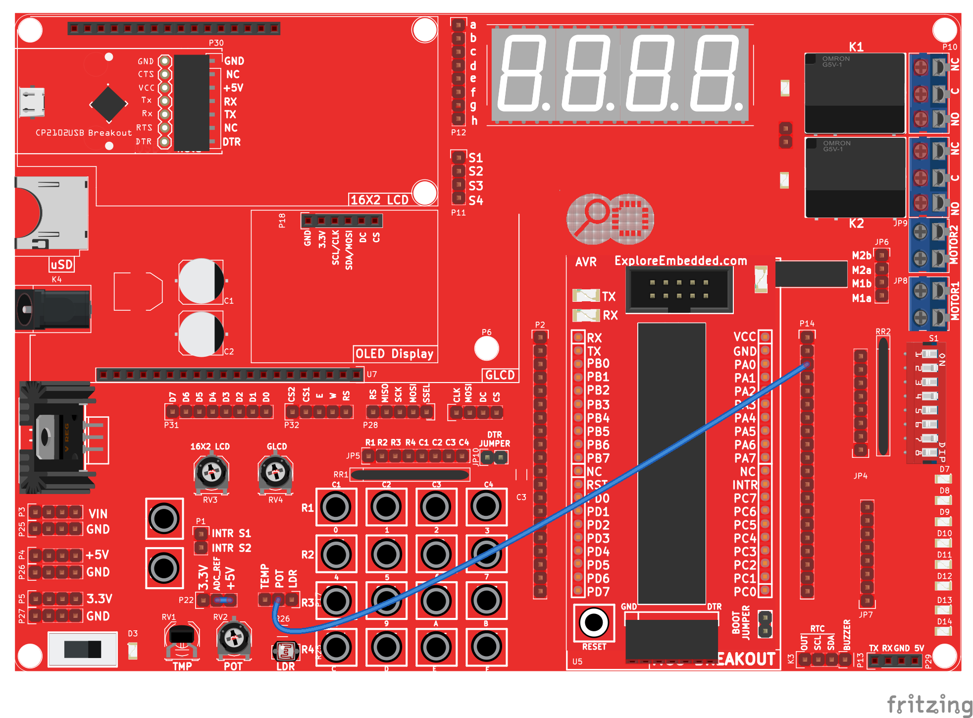
Let's put all of the above together to read raw data from the ADC. We will connect a Potentiometer(Pot) to channel 0, vary it and read the raw voltage.
Hookup Pot
Code to Read Voltage
Temperature
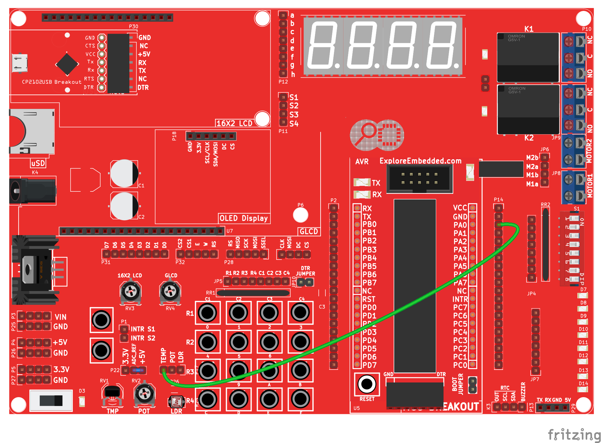
Let's connect the LM35 temperature sensor to channel zero of the ADC and read the temperature. Resolution with 5V reference can be calculated as: $$ResolutionOfADC = (5v/1023)=4.887mv = 5mv$$ For every degree celcius the Lm35 provides 10mv voltage change, therefore $$Temperature = ADCValue/2 $$
Hookup LM35
Code to Read Temperature
Video Tutorial
For those of you, who would like to watch instead of read we have made a video with all the gyan.
Downloads
Download the complete project folder from the below link:
https://github.com/ExploreEmbedded/ATmega32_ExploreUltraAvrDevKit/archive/master.zip
Have a opinion, suggestion , question or feedback about the article let it out here!


