Difference between revisions of "Keil Setup For 8051"
| (2 intermediate revisions by the same user not shown) | |||
| Line 1: | Line 1: | ||
[[Category:8051_tutorials]] | [[Category:8051_tutorials]] | ||
| − | + | In this tutorial we see how to setup Keil4 for generating .hex file.<br> | |
| − | + | Keil software can be downloaded from [https://github.com/ExploreEmbedded/Keil4_For_8051/archive/master.zip this link].<br> | |
| + | Download and install the Keil C51 for 8051.<br> | ||
| + | [[FILE:01Kiel.PNG]]<br> | ||
| − | |||
| − | |||
| − | |||
| − | |||
| − | |||
| − | |||
| − | |||
| − | |||
| − | |||
| − | |||
| − | |||
| − | |||
| − | |||
| − | |||
| − | + | =Keil Setup Steps= | |
| − | + | <b>Step1:</b> Open the Keil software and select the New Microvision project from Project Menu as shown below.<br> | |
| − | + | [[FILE:8051_Keil_01.png]]<br> | |
| − | + | ||
| − | [[ | + | |
| − | + | ||
| − | + | ||
| − | + | ||
| − | + | ||
| − | + | <b>Step2:</b> Browse to your project folder and provide the project name and save it.<br> | |
| − | + | [[FILE:8051_Keil_02.png]]<br> | |
| − | + | ||
| − | + | ||
| − | + | ||
| − | < | + | |
| − | + | ||
| − | + | ||
| − | + | ||
| − | + | ||
| − | + | ||
| − | + | ||
| − | + | ||
| − | + | ||
| − | + | ||
| − | + | ||
| − | + | ||
| − | + | ||
| − | + | ||
| − | + | ||
| − | + | ||
| − | + | ||
| − | + | ||
| − | + | ||
| − | + | ||
| − | + | ||
| − | + | ||
| − | + | ||
| − | + | ||
| − | + | ||
| − | + | ||
| − | + | ||
| − | + | ||
| − | + | ||
| − | + | ||
| − | + | ||
| − | + | ||
| − | + | ||
| − | [[ | + | |
| − | + | ||
| + | <b>Step3:</b> Once the project is saved a new pop up “Select Device for Target” opens, Select the required 8051 series controller and click on OK.<br> | ||
| + | #Atmel->AT89s52<br> | ||
| + | #NXP->P89V51RD2<br> | ||
| + | #Nuvoton-> W78E052D<br> | ||
| + | Since all the controller follow the same 8051 architecture, any of the above mentioned controller can be selected. | ||
| + | [[FILE:8051_Keil_03.png]]<br> | ||
| + | <b>Step4:</b>Select Atmel->At89s52 and click OK.<br> | ||
| + | [[FILE:8051_Keil_04.png]]<br> | ||
| + | <b>Step5:</b>8051 doesn't need the startup code, click on <b>NO</b> option to proceed.<br> | ||
| + | [[FILE:8051_Keil_05.png]]<br> | ||
| + | <b>Step6:</b> Create a new file to write the program.<br> | ||
| + | [[FILE:8051_Keil_06.png]]<br> | ||
| + | <b>Step7:</b> Type the code or Copy paste the below code snippet and save the file as main.c<br> | ||
| + | [[FILE:8051_Keil_07.png]] | ||
| + | <html> | ||
| + | <script src="https://gist.github.com/sharanago/16048113a83ad744505631bc67fdefcc.js"></script> | ||
| + | </html> | ||
| + | <br> | ||
| + | <b>Step8:</b>Save the file as main.c<br> | ||
| + | [[FILE:8051_Keil_08.png]]<br> | ||
| + | <b>Step9:</b>Add the file to the project using the option <b>Add files to Source Group</b>.<br> | ||
| + | [[FILE:8051_Keil_09.png]]<br> | ||
| + | <b>Step10:</b> Add the recently saved file to the project.<br> | ||
| + | [[FILE:8051_Keil_10.png]]<br> | ||
| + | <b>Step11:</b>Now the main.c file should appear in Project Source Group.<br> | ||
| + | [[FILE:8051_Keil_11.png]]<br> | ||
| + | <b>Step12:</b>Build the project and fix the compiler errors/warnings if any. | ||
| + | [[FILE:8051_Keil_12.png]]<br> | ||
| + | <b>Step13:</b>Code gets compiled with no errors and .hex file is still not generated.<br> | ||
| + | [[FILE:8051_Keil_13.png]]<br> | ||
| + | =Enable Hex File Generation= | ||
| + | <b>Step14:</b>Click on <b>Target Options</b> to select the option for generating .hex file.<br> | ||
| + | [[FILE:8051_Keil_14.png]]<br> | ||
| + | <b>Step15:</b> Rebuild the target to generate the .hex file. <br> | ||
| + | [[FILE:8051_Keil_15.png]]<br> | ||
| + | <b>Step16:</b> Check teh project folder for generated .hex file. | ||
| + | [[FILE:8051_Keil_16.png]]<br> | ||
| + | =Uploading the Hex file= | ||
| + | After generating the .hex file check the below tutorials for uploading it. | ||
| + | # [[Uploading Hex File Using nuvoTon|Uploading Hex File Using nuvoTon ISP.]] | ||
| + | # [[Uploading Hex File Using At89s52 ISP Programmer|Uploading Hex File To At89s52 using ISP Using Programmer.]] | ||
| + | <br><br> | ||
| − | + | Have a opinion, suggestion , question or feedback about the article let it out here! | |
{{DISQUS}} | {{DISQUS}} | ||
Latest revision as of 17:36, 19 August 2016
In this tutorial we see how to setup Keil4 for generating .hex file.
Keil software can be downloaded from this link.
Download and install the Keil C51 for 8051.
Keil Setup Steps
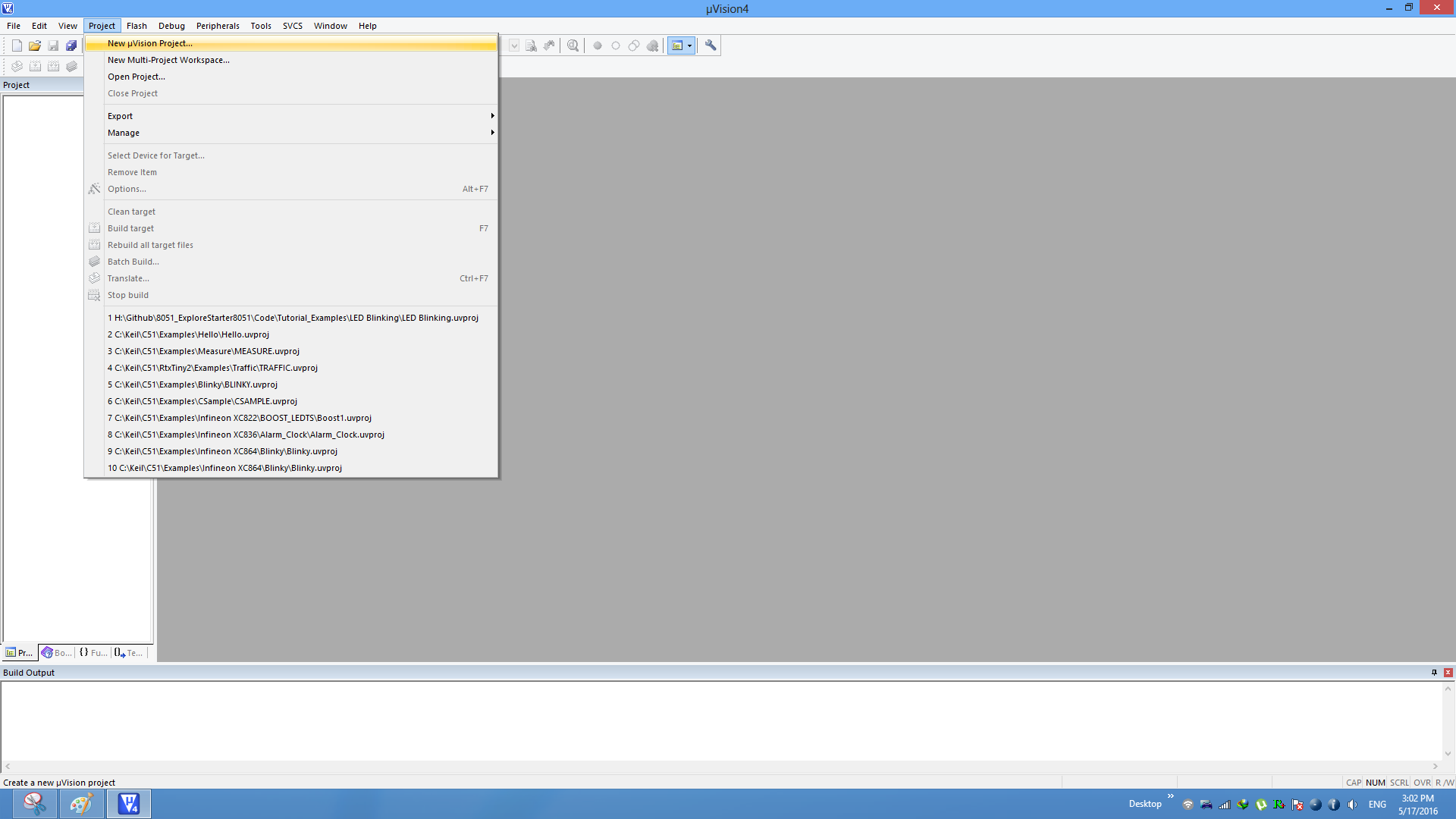
Step1: Open the Keil software and select the New Microvision project from Project Menu as shown below.
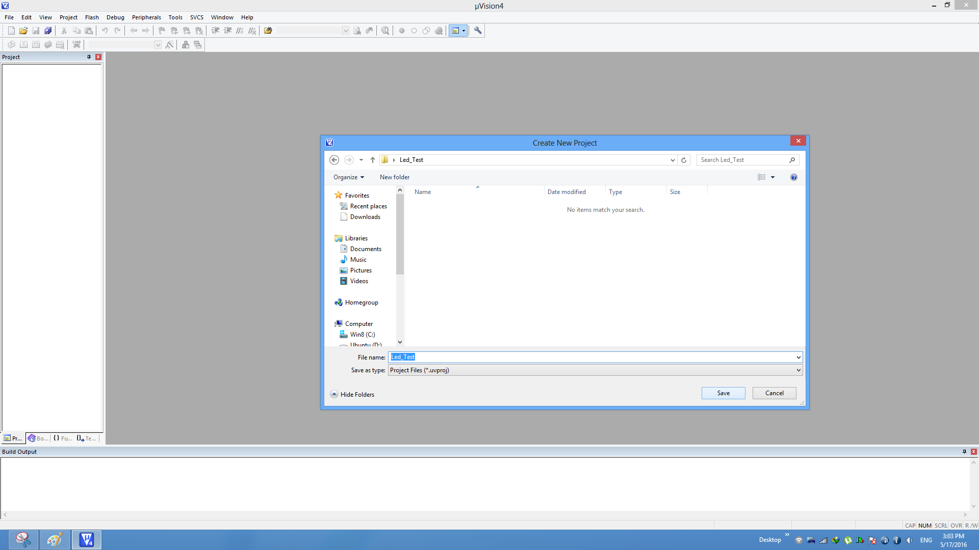
Step2: Browse to your project folder and provide the project name and save it.
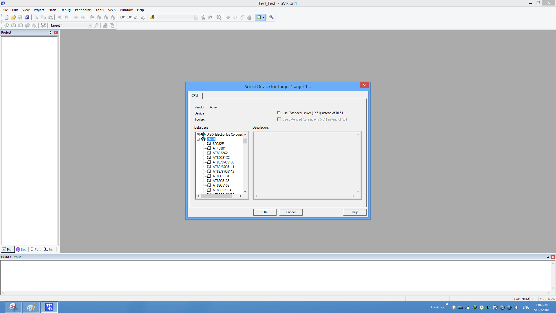
Step3: Once the project is saved a new pop up “Select Device for Target” opens, Select the required 8051 series controller and click on OK.
- Atmel->AT89s52
- NXP->P89V51RD2
- Nuvoton-> W78E052D
Since all the controller follow the same 8051 architecture, any of the above mentioned controller can be selected.
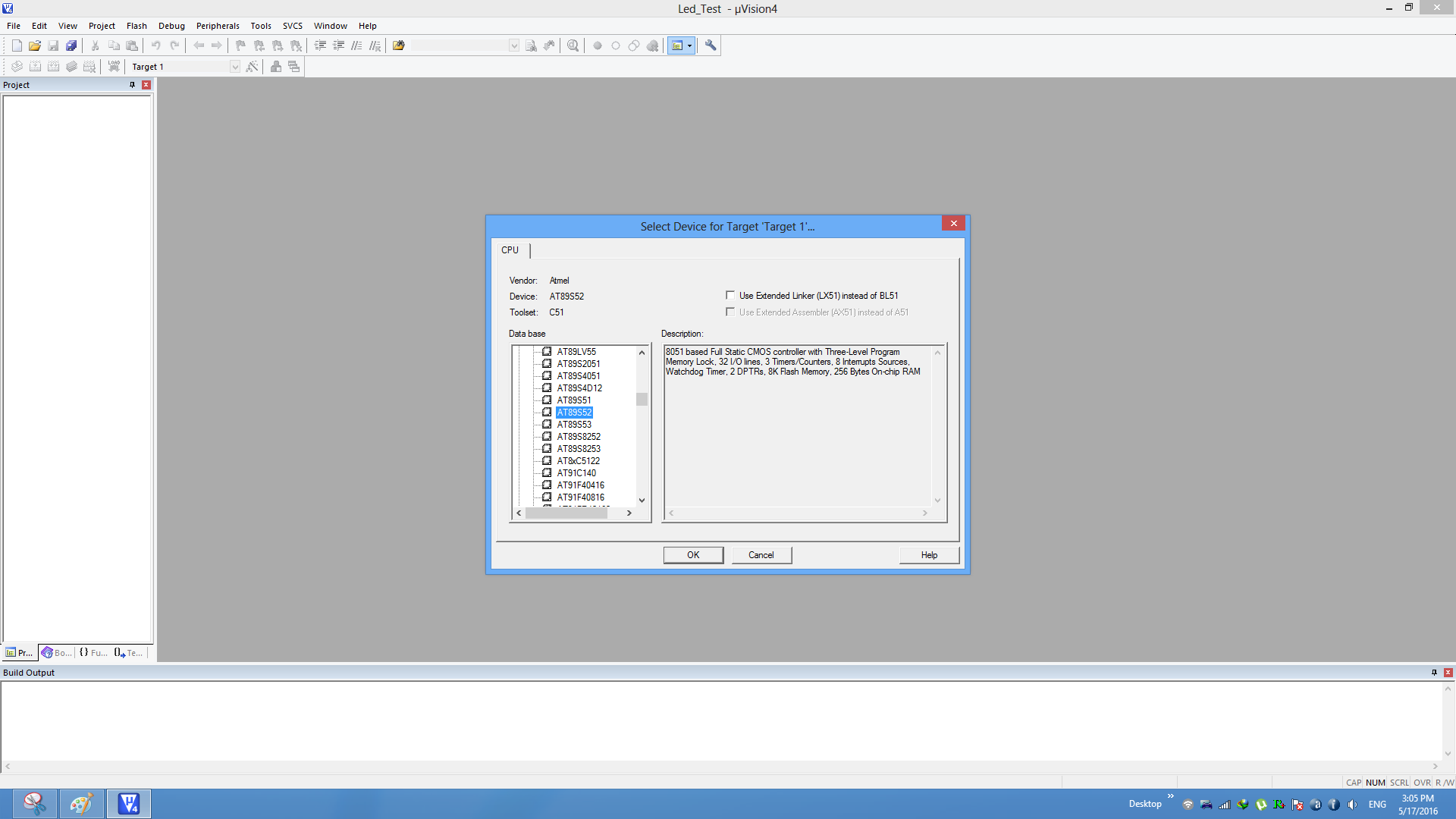
Step4:Select Atmel->At89s52 and click OK.
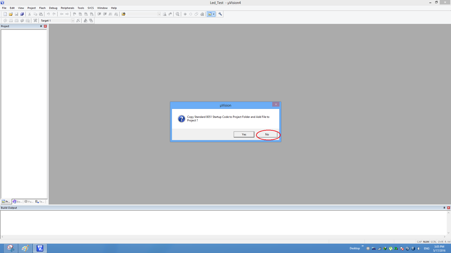
Step5:8051 doesn't need the startup code, click on NO option to proceed.
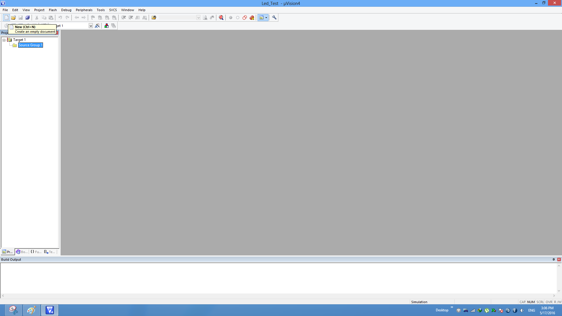
Step6: Create a new file to write the program.
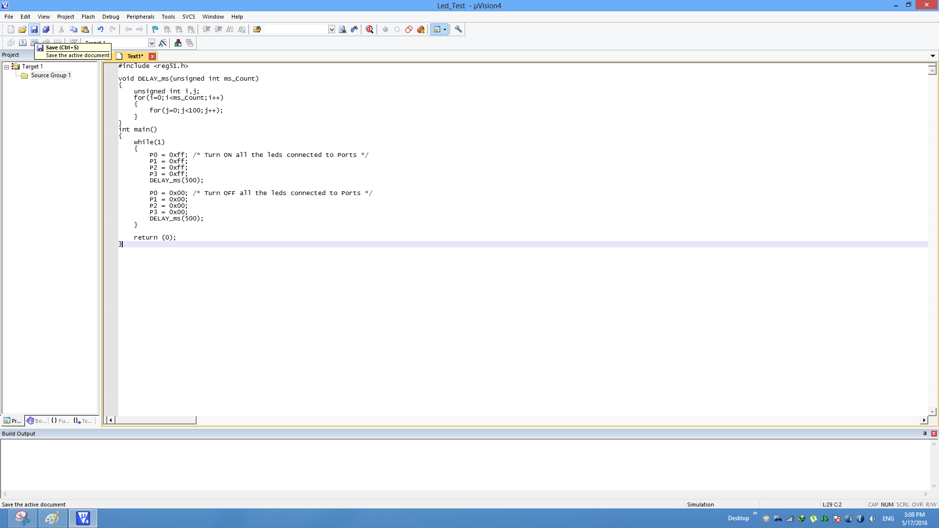
Step7: Type the code or Copy paste the below code snippet and save the file as main.c
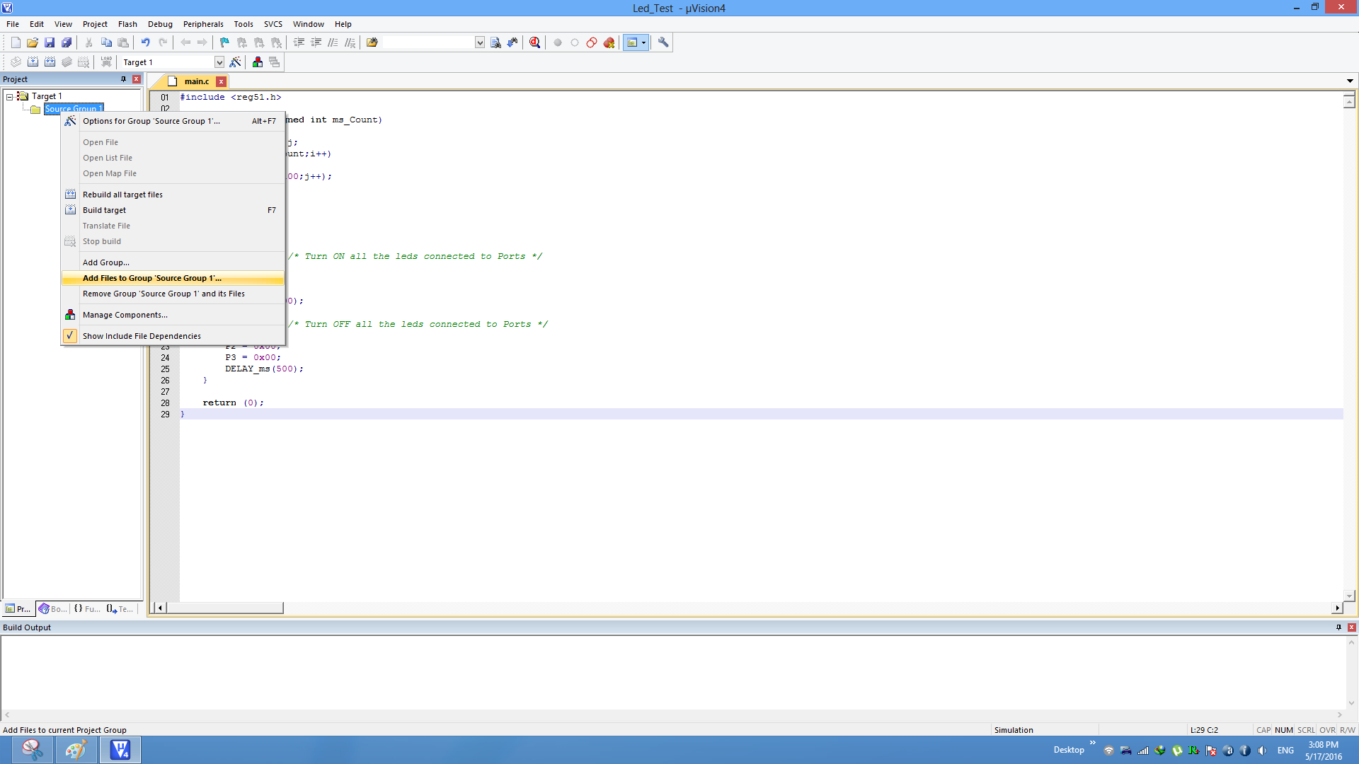
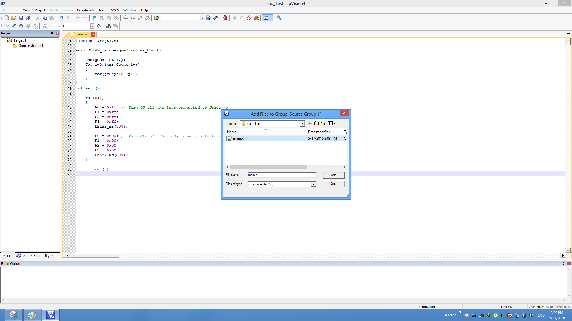
Step9:Add the file to the project using the option Add files to Source Group.
Step10: Add the recently saved file to the project.
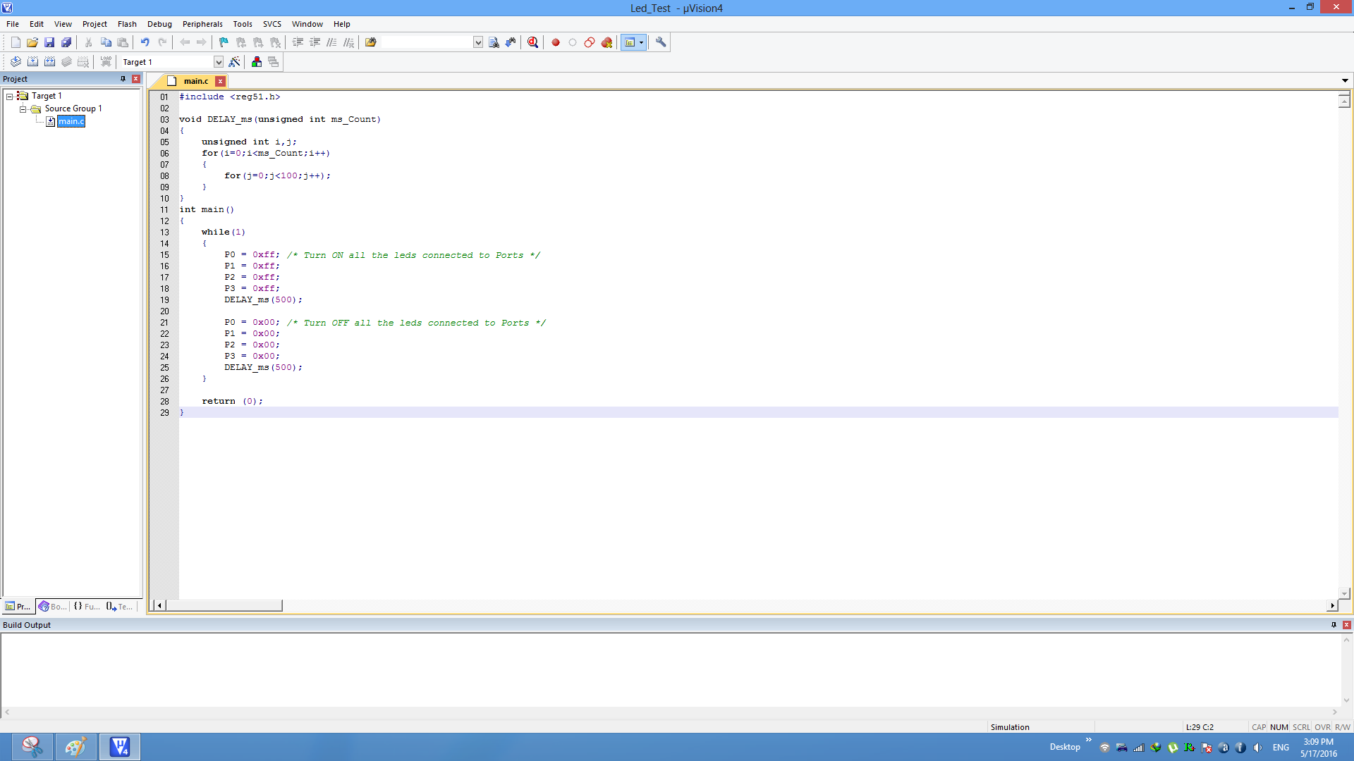
Step11:Now the main.c file should appear in Project Source Group.
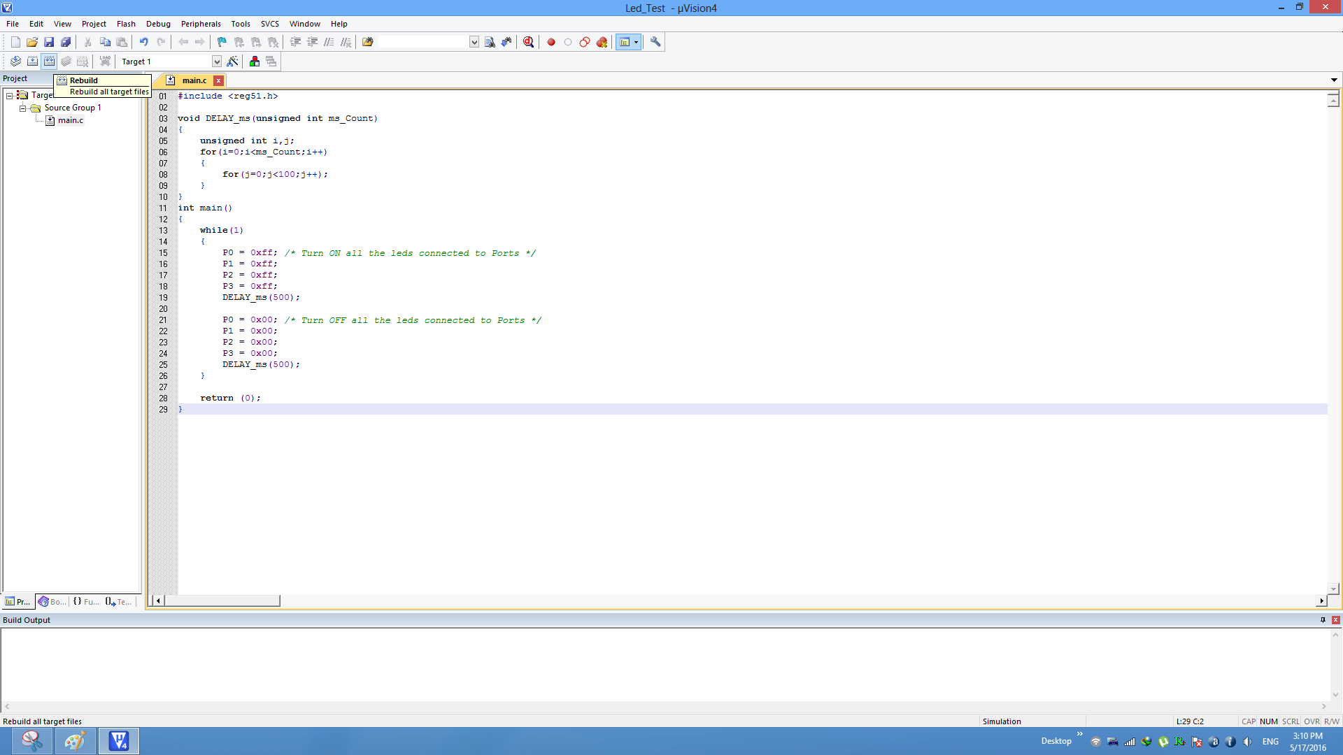
Step12:Build the project and fix the compiler errors/warnings if any.
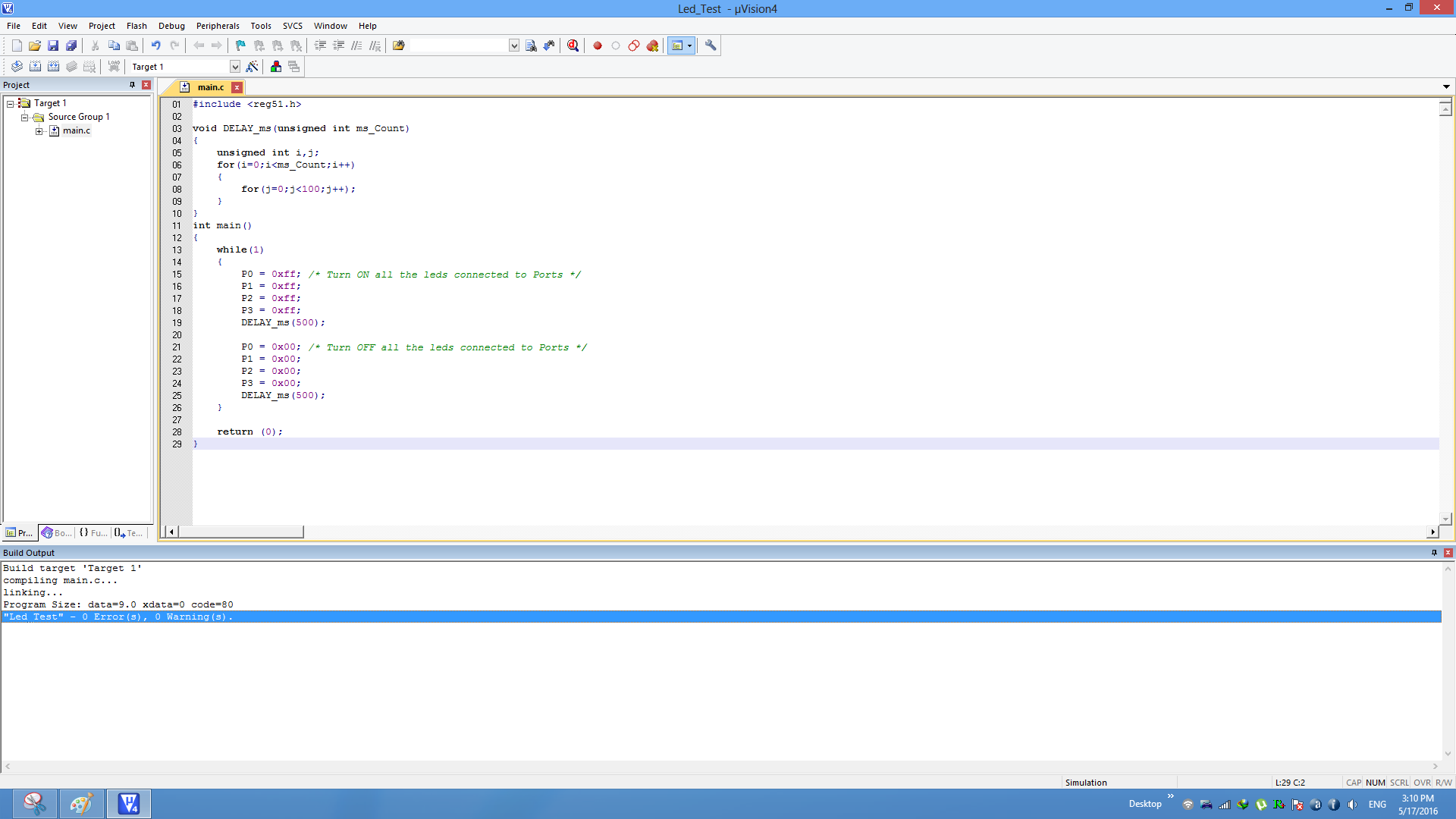
Step13:Code gets compiled with no errors and .hex file is still not generated.
Enable Hex File Generation
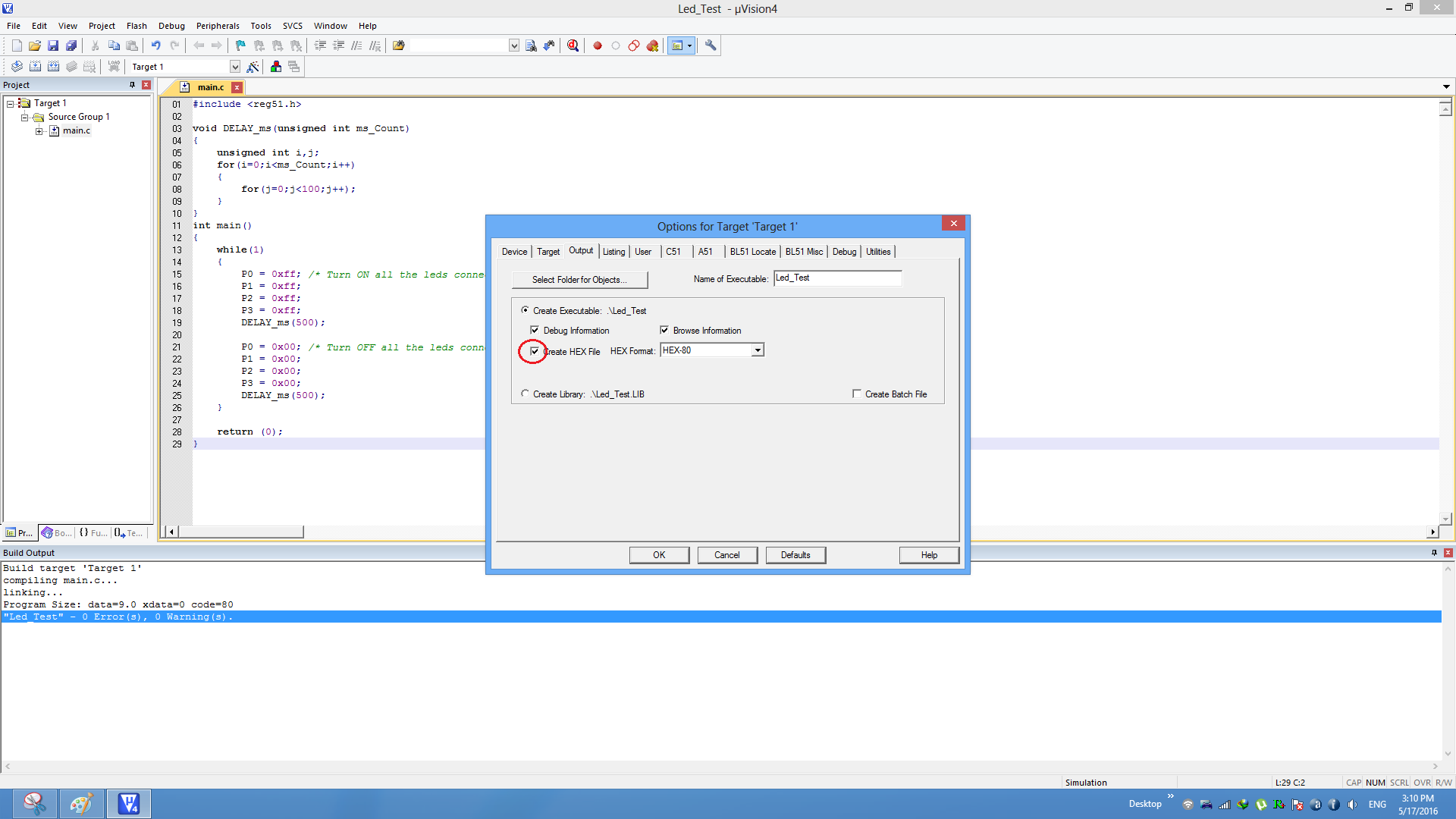
Step14:Click on Target Options to select the option for generating .hex file.
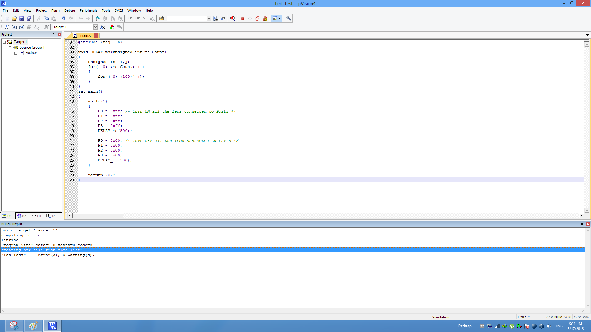
Step15: Rebuild the target to generate the .hex file.
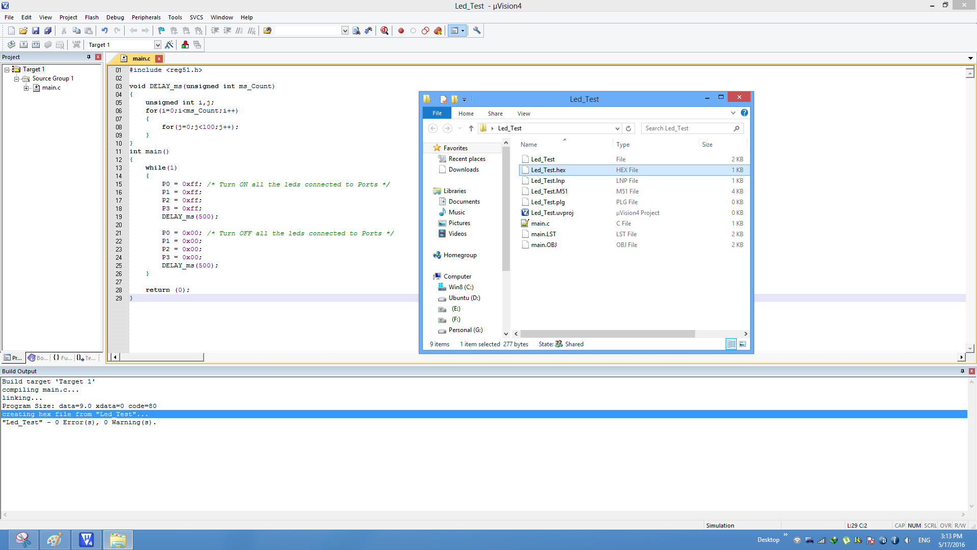
Step16: Check teh project folder for generated .hex file.
Uploading the Hex file
After generating the .hex file check the below tutorials for uploading it.
Have a opinion, suggestion , question or feedback about the article let it out here!


