Difference between revisions of "PIC Starter USB Development Board"
(Created page with "{{Box|type=l_green_light|text= ''The Ultimate PIC Starter USB Development Board comes with PIC 16F877A MCU with inbuilt serial bootloader, USB to UART convertor eliminating ne...") |
|||
| (25 intermediate revisions by 6 users not shown) | |||
| Line 1: | Line 1: | ||
| + | [[Category:PIC Development Boards]] | ||
{{Box|type=l_green_light|text= | {{Box|type=l_green_light|text= | ||
''The Ultimate PIC Starter USB Development Board comes with PIC 16F877A MCU with inbuilt serial bootloader, USB to UART convertor eliminating need of a external programmer! The board also has 16x2 LCD Breakout, test switch, LEDs and all pins of the MCU taken out. This will help you get started with PIC development.'' | ''The Ultimate PIC Starter USB Development Board comes with PIC 16F877A MCU with inbuilt serial bootloader, USB to UART convertor eliminating need of a external programmer! The board also has 16x2 LCD Breakout, test switch, LEDs and all pins of the MCU taken out. This will help you get started with PIC development.'' | ||
}} | }} | ||
| + | [[File:Cart add.png|right|link=https://www.exploreembedded.com/product/PIC%20Starter%2016F877A%20USB%20Development%20Board]] | ||
| + | [[File:DSC00830.JPG |x300px]] | ||
| + | |||
| + | |||
| + | <gallery mode = "packed" > | ||
| + | |||
| + | File:DSC00833.JPG | ||
| + | File:DSC00836.JPG | ||
| + | File:DSC00839.JPG | ||
| + | File:DSC01045.JPG | ||
| + | File:PIC Starter USB With LCD 3d.JPG | ||
| + | </gallery> | ||
| + | {{Box|type=blue_dark|text= | ||
| + | Features: | ||
| + | }} | ||
| + | {{Box|type=l_green_light|text=<br /> | ||
| + | |||
| + | *16F877A MCU with ds30 bootloader | ||
| + | *LCD 16x2 breakout. | ||
| + | *Serial Interface RS232. | ||
| + | *Test switches (1) and LEDs(3). | ||
| + | *All Port pins pins available for peripheral interfacing. | ||
| + | *Dimensions: 95mm X 70mm. | ||
| + | *1.6mm Glass Epoxy, FR4 PCB. | ||
| + | *Wave Soldered. | ||
| + | }} | ||
| + | |||
| + | |||
| + | {{Box|type=blue_dark|text= | ||
| + | Flashing the Hex file using ds30 bootloader}} | ||
| + | {{Box|type=l_green_light|text= | ||
| + | STEP 1: [http://exploreembedded.com/wiki/File:Ds30LoaderGui.zip '''Download'''] and install the DS30 bootloader gui. | ||
| + | |||
| + | Step 2: | ||
| + | [[File:DS30 Step0.PNG|x400px|Setup Parameters]] | ||
| + | *Browse the hex file | ||
| + | *Select the appropriate MCU | ||
| + | *'''Select the baud rate as 9600''' | ||
| + | *'''Select the correct com port detected on your computer, when using USB to serial convertor check for exact COM port number in device manager''' | ||
| + | |||
| + | Step 3: The board uses DTR pin of the CP2102 USB to Serial Convertor to reset the MCU. Set it up as shown in the image below. | ||
| + | |||
| + | [[File:AUTO RESET.png|x300px|Setup AutoReset]] | ||
| + | |||
| + | Step 4: Click on the write option to flash the hex file,. Images below show the sequence. | ||
| + | |||
| + | <hovergallery maxhoverwidth=600 maxhoverheight=600> | ||
| + | File:DS30 Step2.PNG|...detects bootloader | ||
| + | File:DS30_Step3.PNG|...finishes flashing. | ||
| + | </hovergallery> | ||
| + | }} | ||
| + | |||
| + | {{Box|type=blue_dark|text=Downloads}} | ||
| + | {{Box|type=l_green_light|text=<br /> | ||
| + | *[https://github.com/ExploreEmbedded/PIC-Starter-USB-Development-Board_DVB-13001/archive/master.zip Sample Code] | ||
| + | *[https://www.exploreembedded.com/wiki/images/a/a5/PIC_Starter_USB_Schematic.pdf Schematic] | ||
| + | }} | ||
| + | {{DISQUS}} | ||
Latest revision as of 16:36, 16 September 2015
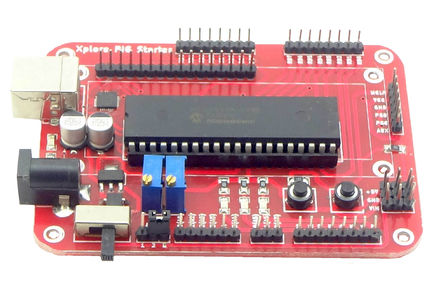
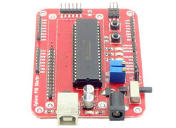
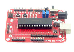
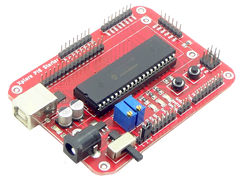
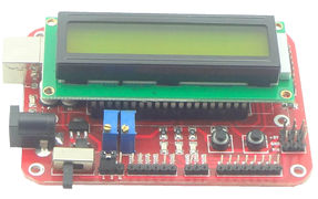
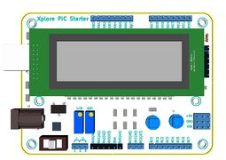
The Ultimate PIC Starter USB Development Board comes with PIC 16F877A MCU with inbuilt serial bootloader, USB to UART convertor eliminating need of a external programmer! The board also has 16x2 LCD Breakout, test switch, LEDs and all pins of the MCU taken out. This will help you get started with PIC development.
Features:
- 16F877A MCU with ds30 bootloader
- LCD 16x2 breakout.
- Serial Interface RS232.
- Test switches (1) and LEDs(3).
- All Port pins pins available for peripheral interfacing.
- Dimensions: 95mm X 70mm.
- 1.6mm Glass Epoxy, FR4 PCB.
- Wave Soldered.
Flashing the Hex file using ds30 bootloader
STEP 1: Download and install the DS30 bootloader gui.
- Browse the hex file
- Select the appropriate MCU
- Select the baud rate as 9600
- Select the correct com port detected on your computer, when using USB to serial convertor check for exact COM port number in device manager
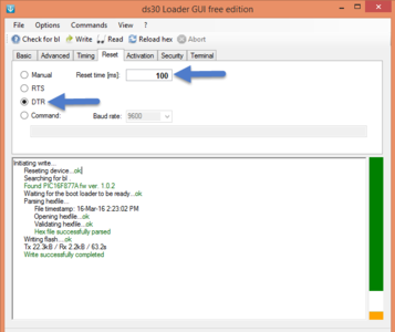
Step 3: The board uses DTR pin of the CP2102 USB to Serial Convertor to reset the MCU. Set it up as shown in the image below.
Step 4: Click on the write option to flash the hex file,. Images below show the sequence.
<hovergallery maxhoverwidth=600 maxhoverheight=600> File:DS30 Step2.PNG
Downloads


