Difference between revisions of "PIC 16F877A Starter Kit with bootloader"
(Created page with "[[File:{{#setmainimage:Pro_PIC_back.jpg}}|720x450px|Fig 1:Pro PIC]] <br /> {{Box|type=l_green_light|text= Pro_PIC is designed to carry out academic projects around the 40 pi...") |
|||
| (6 intermediate revisions by the same user not shown) | |||
| Line 1: | Line 1: | ||
| − | [[File:{{#setmainimage: | + | {{Popup|type=l|text=This product has been discontinued, we have newer version [[PIC_Starter_USB_Development_Board|check it]]}} |
| + | [[File:{{#setmainimage:PIC_Starter_Kit_2.jpg}}|710x450px|Fig 1:Pro PIC]] | ||
<br /> | <br /> | ||
| + | {{Popup|type=d|text=This product has been discontinued, we have newer version [[PIC_Starter_USB_Development_Board|check it]]}} | ||
| + | [[category:PIC Development Boards]] | ||
{{Box|type=l_green_light|text= | {{Box|type=l_green_light|text= | ||
| − | + | PIC Starter Kit is a 40 pin starter development kit based on 16f877a Microcontroller. It comes with inbuilt bootloader eliminating the need of expensive external programmer. | |
| − | + | ||
| − | + | ||
}} | }} | ||
| − | + | <hovergallery maxhoverwidth=600 maxhoverheight=600> | |
| − | + | File:PIC_Starter_Kit_2.jpg|The Development Board | |
| − | + | File:PIC Starter Kit kitcontents 3.jpg|Kit Contents | |
| + | File:PIC_Starter_Kit_2.jpg|Complete board, RTC visible after taking of LCD. | ||
| + | </hovergallery> | ||
{{Box|type=blue_dark|text= | {{Box|type=blue_dark|text= | ||
Features: | Features: | ||
}} | }} | ||
| − | {{Box|type=l_green_light|text= | + | {{Box|type=l_green_light|text= |
| − | *LCD | + | *16F877a MCU with bootloader |
| − | *Real time clock. | + | *LCD 16x2 . |
| + | *Real time clock based on DS 1307. | ||
*Serial Interface RS232. | *Serial Interface RS232. | ||
*Test switches (4) and LEDs(4). | *Test switches (4) and LEDs(4). | ||
| − | + | *All Port pins pins available for peripheral interfacing. | |
| − | *All | + | |
| − | + | ||
| − | + | ||
| − | + | ||
| − | + | ||
| − | + | ||
| − | + | ||
*Dimensions: 95mm X 95mm. | *Dimensions: 95mm X 95mm. | ||
*1.6mm Glass Epoxy, FR4 PCB. | *1.6mm Glass Epoxy, FR4 PCB. | ||
*Wave Soldered. | *Wave Soldered. | ||
}} | }} | ||
| − | + | {{Box|type=blue_dark|text= | |
| − | + | Kit Contains: | |
| − | + | }} | |
| − | + | {{Box|type=l_green_light|text= | |
| + | 1. PIC starter Development Board with ICs and LCD 16x2 <br/> | ||
| + | 2. Serial Cable<br/> | ||
| + | 3. Power Adapter<br/> | ||
| + | 4. 10xFemale to Female connectors.<br/> | ||
| + | }} | ||
| + | {{Box|type=blue_dark|text= | ||
| + | Flashing the Hex file using ds30 bootloader}} | ||
| + | {{Box|type=l_green_light|text= | ||
| + | STEP 1: [http://xplorelabz.com/wiki/images/6/62/Ds30_Loader.rar Download]and install the DS30 bootloader gui. | ||
| + | Step 2: | ||
| + | [[File:DS30 Step0.PNG|x400px|Setup Parameters]] | ||
| + | *Browse the hex file | ||
| + | *Select the appropriate MCU | ||
| + | *'''Select the baud rate as 9600''' | ||
| + | *'''Select the correct com port detected on your computer, when using USB to serial convertor check for exact COM port number in device manager''' | ||
| + | Step 3: Click on the write option to flash the hex file, '''RESET the board immediately so that bootloader is detected'''. Images below show the sequence. | ||
| + | <hovergallery maxhoverwidth=600 maxhoverheight=600> | ||
| + | File:DS30 Step1.PNG|Press reset the board | ||
| + | File:DS30 Step2.PNG|...detects bootloader | ||
| + | File:DS30_Step3.PNG|...finishes flashing. | ||
| + | </hovergallery> | ||
| + | }} | ||
{{#seo: | {{#seo: | ||
| − | |||
|title=PIC_Development_Boards | |title=PIC_Development_Boards | ||
| − | |||
|titlemode=append | |titlemode=append | ||
| − | |||
|keywords=PIC,AT89s51,at89c51,p89v51rd2,xplorelabz,tutorials,PIC development boards,PIC boards,PIC board,Pro pic | |keywords=PIC,AT89s51,at89c51,p89v51rd2,xplorelabz,tutorials,PIC development boards,PIC boards,PIC board,Pro pic | ||
| − | |||
|description=PIC Development Boards | |description=PIC Development Boards | ||
| − | |||
}} | }} | ||
| − | |||
{{DISQUS}} | {{DISQUS}} | ||
Latest revision as of 15:30, 25 June 2014
This product has been discontinued, we have newer version check it

This product has been discontinued, we have newer version check it
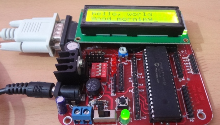
PIC Starter Kit is a 40 pin starter development kit based on 16f877a Microcontroller. It comes with inbuilt bootloader eliminating the need of expensive external programmer.
Features:
*16F877a MCU with bootloader
- LCD 16x2 .
- Real time clock based on DS 1307.
- Serial Interface RS232.
- Test switches (4) and LEDs(4).
- All Port pins pins available for peripheral interfacing.
- Dimensions: 95mm X 95mm.
- 1.6mm Glass Epoxy, FR4 PCB.
- Wave Soldered.
Kit Contains:
1. PIC starter Development Board with ICs and LCD 16x2
2. Serial Cable
3. Power Adapter
4. 10xFemale to Female connectors.
2. Serial Cable
3. Power Adapter
4. 10xFemale to Female connectors.
Flashing the Hex file using ds30 bootloader
STEP 1: Downloadand install the DS30 bootloader gui.
Step 2:


- Browse the hex file
- Select the appropriate MCU
- Select the baud rate as 9600
- Select the correct com port detected on your computer, when using USB to serial convertor check for exact COM port number in device manager
Step 3: Click on the write option to flash the hex file, RESET the board immediately so that bootloader is detected. Images below show the sequence. <hovergallery maxhoverwidth=600 maxhoverheight=600> File:DS30 Step1.PNG
