Difference between revisions of "Interfacing RTC with AVR Breakout"
| (2 intermediate revisions by the same user not shown) | |||
| Line 14: | Line 14: | ||
<script src="https://gist.github.com/Xplorer001/dabc20ebd54d261f07f0.js"></script> | <script src="https://gist.github.com/Xplorer001/dabc20ebd54d261f07f0.js"></script> | ||
</html> | </html> | ||
| + | |||
| + | <br/> | ||
| + | [[file:00Interface RTC with Atmega128.gif]] | ||
| + | =Downloads= | ||
| + | Download the complete project folder from the below link: | ||
| + | https://github.com/ExploreEmbedded/AVR-MCU-Breakout-Board/archive/master.zip<br> | ||
| + | |||
| + | |||
| + | |||
| + | Have a opinion, suggestion , question or feedback about the article let it out here! | ||
| + | {{DISQUS}} | ||
Latest revision as of 10:17, 20 April 2016
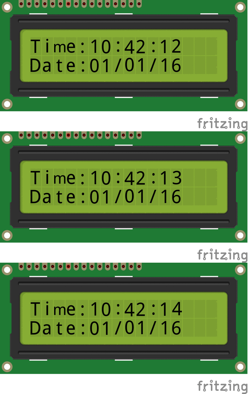
Now in this tutorial we will interface RTC (Real time clock) with Atmega32 breakout board. For this tutorial we will require RTC Breakout ,LCD Breakout and 16x2 LCD to display the time.
Contents
Basics
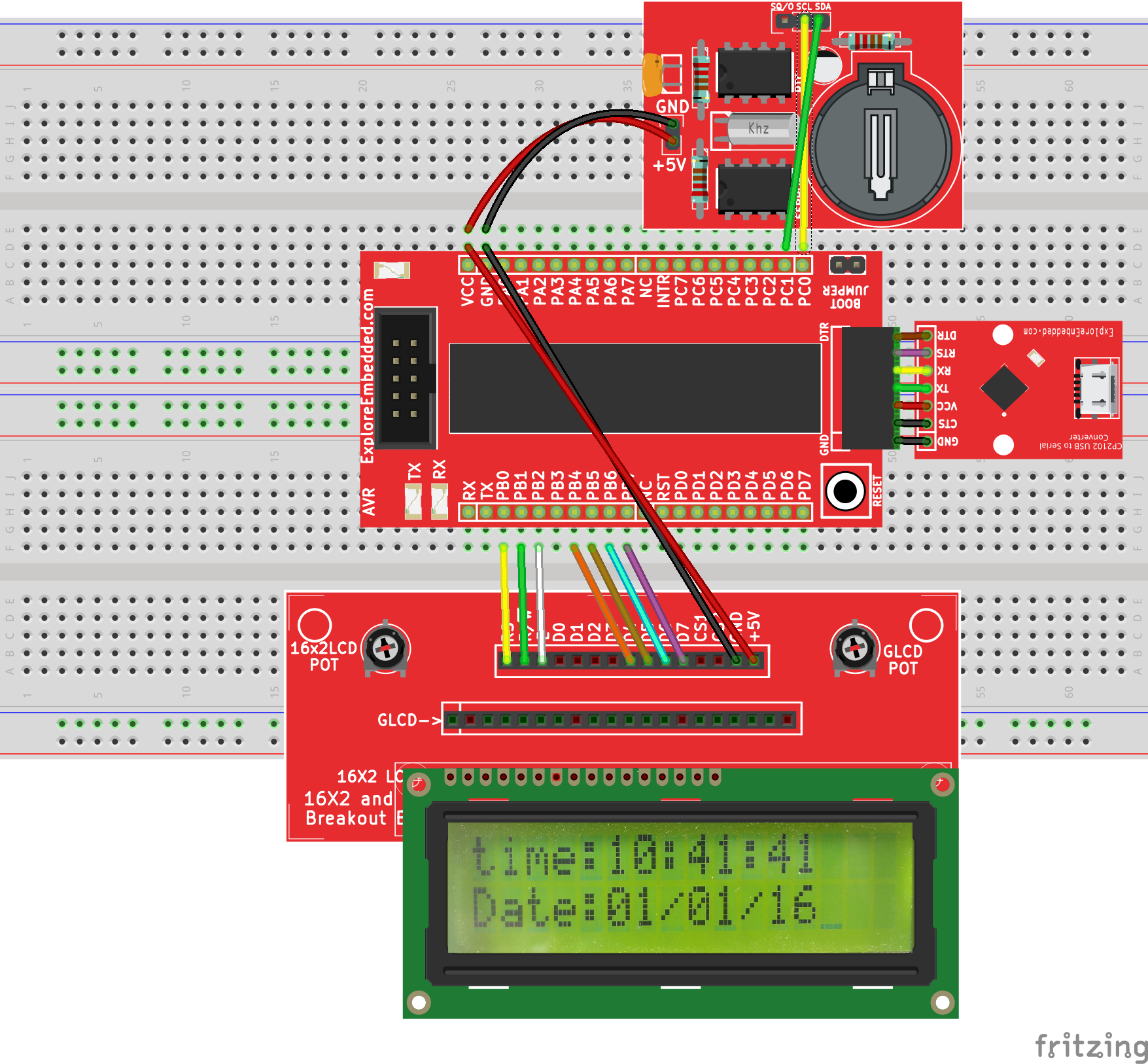
In this example we are using DS1307 RTC. It will communicate through I2C protocol with controller. Connect SCL and SDA of RTC Breakout to SCL and SDA of ATmega32. Connect D4 to D7 of LCD Breakout to PORT B4 to PORT B7
and RS,R/W,E to PORT B0 to PORT B2 respectively as shown in hook up.
Refer Real Time Clock(DS1307) with AVR tutorial for RTC basics.
Hook Up
Code
Downloads
Download the complete project folder from the below link:
https://github.com/ExploreEmbedded/AVR-MCU-Breakout-Board/archive/master.zip
Have a opinion, suggestion , question or feedback about the article let it out here!


