Difference between revisions of "Switch and LED with Starter AVR"
| Line 1: | Line 1: | ||
[[category:Starter AVR]] | [[category:Starter AVR]] | ||
| − | + | In this tutorial we will look at how to read the status of a switch and control the led depending on the switch status. | |
| + | Refer the [[AVR I/O Register Configuration]] tutorial for basics of GPIO register configuration. | ||
=Basic= | =Basic= | ||
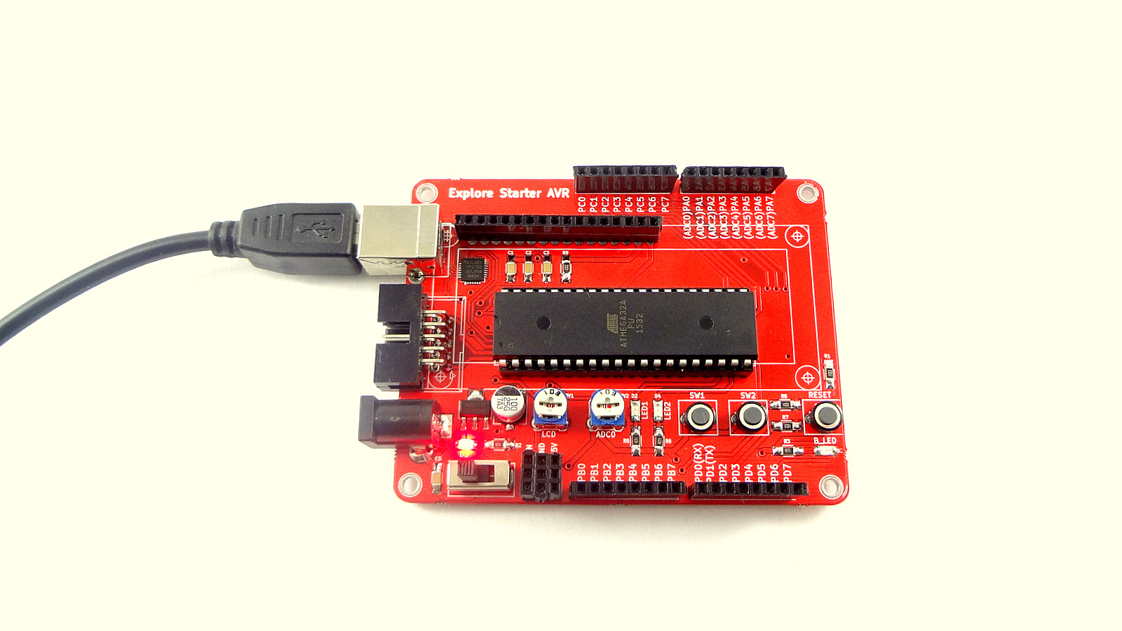
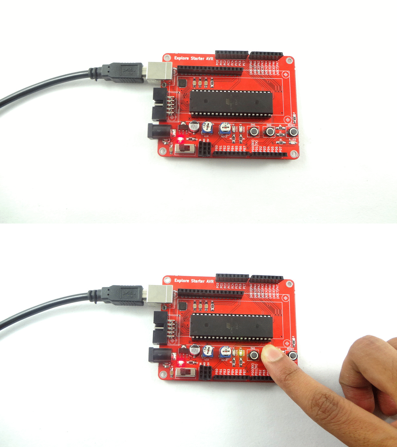
| + | Starter AVR has ATmega32 micro controller and has two LED's and two user switches on board. we'll use the same for this example so no extra hardware is required. I am using switch connected to PD3 and LED connected to PD5. Dump the code and press the SW2 on board, you will find that LED2 will change state according to the switch status. | ||
=Hookup= | =Hookup= | ||
[[File:starter2.JPG]] | [[File:starter2.JPG]] | ||
| Line 15: | Line 17: | ||
=Downloads= | =Downloads= | ||
| + | |||
| + | {{DISQUS}} | ||
Revision as of 17:46, 5 April 2016
In this tutorial we will look at how to read the status of a switch and control the led depending on the switch status. Refer the AVR I/O Register Configuration tutorial for basics of GPIO register configuration.
Contents
Basic
Starter AVR has ATmega32 micro controller and has two LED's and two user switches on board. we'll use the same for this example so no extra hardware is required. I am using switch connected to PD3 and LED connected to PD5. Dump the code and press the SW2 on board, you will find that LED2 will change state according to the switch status.
Hookup
Code
Demo
Downloads


