Difference between revisions of "Switch and a LED with Atmega128 Breakout"
Raghavendra (Talk | contribs) |
Raghavendra (Talk | contribs) |
||
| Line 2: | Line 2: | ||
Now we will control the LED depending on external input. In this tutorial we will interface a switch to one of the port pin and display its status on LED connected to other port. | Now we will control the LED depending on external input. In this tutorial we will interface a switch to one of the port pin and display its status on LED connected to other port. | ||
=Basics= | =Basics= | ||
| − | For this tutorial we will a connect a switch to PORT C0 and LED to PORT B0 of | + | For this tutorial we will a connect a switch to PORT C0 and LED to PORT B0 of Atmega128. W will configure PORT A0 as input to read the switch status and PORT C0 as outputto display the switch status on LED. Initially LED will be ON , when we press switch the LED will be OFF. |
<br/> | <br/> | ||
Refer the [[AVR I/O Register Configuration]] tutorial for basics of GPIO register configuration. | Refer the [[AVR I/O Register Configuration]] tutorial for basics of GPIO register configuration. | ||
Revision as of 16:34, 5 April 2016
Now we will control the LED depending on external input. In this tutorial we will interface a switch to one of the port pin and display its status on LED connected to other port.
Contents
Basics
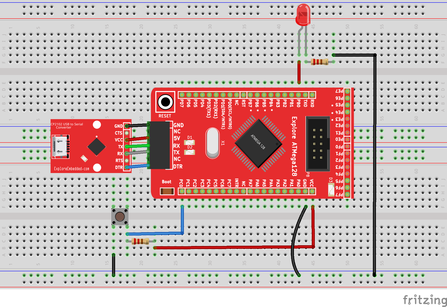
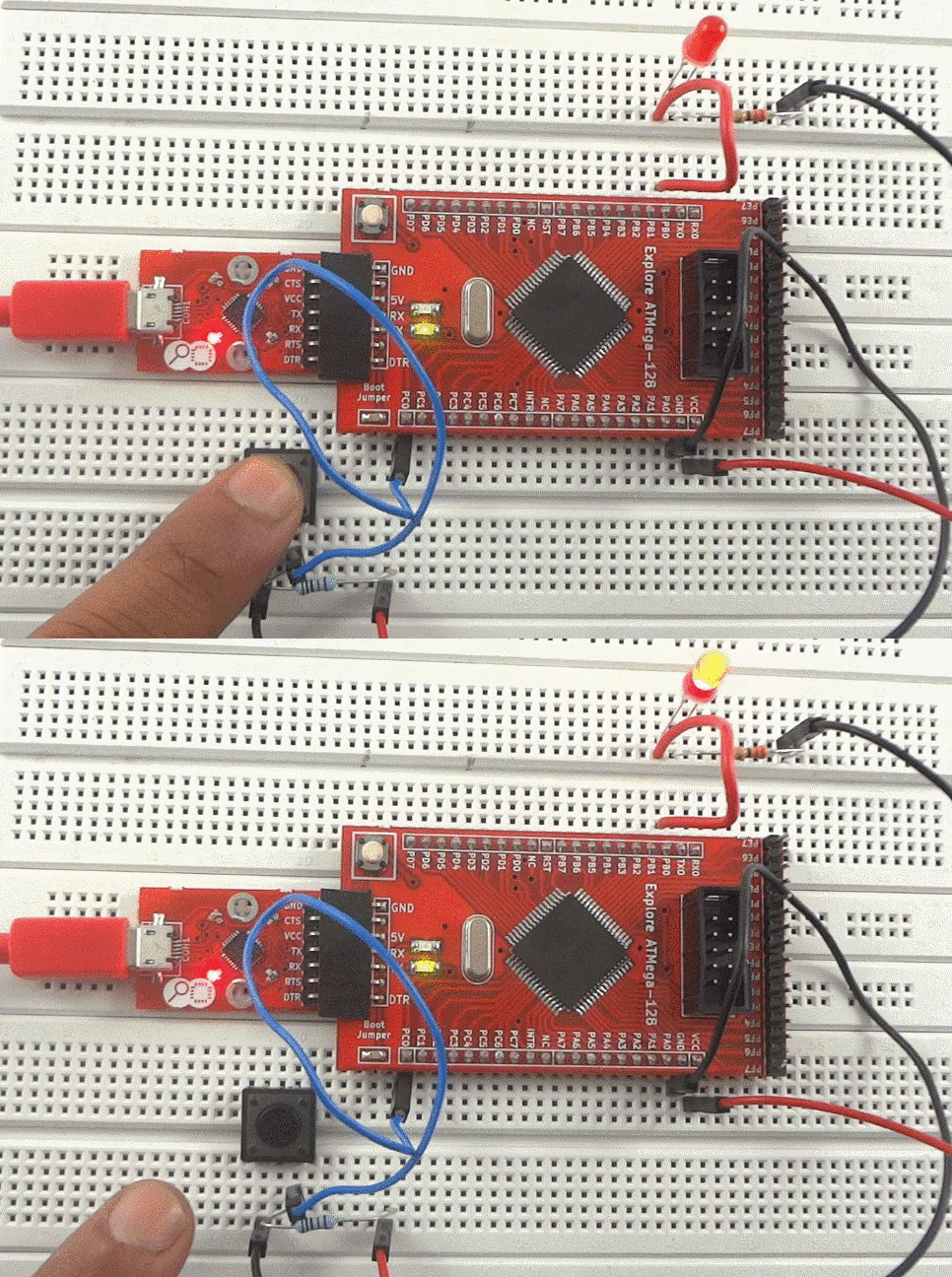
For this tutorial we will a connect a switch to PORT C0 and LED to PORT B0 of Atmega128. W will configure PORT A0 as input to read the switch status and PORT C0 as outputto display the switch status on LED. Initially LED will be ON , when we press switch the LED will be OFF.
Refer the AVR I/O Register Configuration tutorial for basics of GPIO register configuration.
Hook Up
Code


