Difference between revisions of "AVR External Interrupts"
(→Basics) |
|||
| Line 21: | Line 21: | ||
| − | '''MCU Control Register (MCUCR)''' | + | '''MCU Control Register (MCUCR)'''<br /> |
| + | |||
The MCUCR register allows us to configure the type of interrupt we need as shown by the table below: | The MCUCR register allows us to configure the type of interrupt we need as shown by the table below: | ||
{| class="table table-condensed table-bordered" | {| class="table table-condensed table-bordered" | ||
| Line 45: | Line 46: | ||
'''General Interrupt Flag Register(GIFR) | '''General Interrupt Flag Register(GIFR) | ||
''' | ''' | ||
| + | <br /> | ||
| + | The bits of GIFR register are set when an interrupt occurs and cleared when it is processed. | ||
{| class="table table-condensed table-bordered" | {| class="table table-condensed table-bordered" | ||
|- | |- | ||
Revision as of 18:06, 19 March 2016
We have looked at the basics of AVR Interrupts, now let us go ahead and use the External Interrupts feature on the AVR MCUs.
Contents
Basics
Steps to configure the Interrupts:
- Set INT1 and INT0 bits in the General Interrupt Control Register (GICR)
- Configure MCU Control Register (MCUCR) to select interrupt type.
- Set Global Interrupt(I-bit) Enable bit in the AVR Status Register(SREG)
- Handle the interrupt in the Interrupt Service Routine code.
General Interrupt Control Register (GICR)
The GICR Register shown below is used to enable INT0 and INT1 interrupts. These interrupts correspond to the two physical pins PD3 and PD4 respectively. The INT0 is configured to produce low level triggered and INT1 as falling edge triggered interrupt respectively. A counter is increment and displayed when the interrupt occurs.
| 7 | 6 | 5 | 4 | 3 | 2 | 1 | 0 |
|---|---|---|---|---|---|---|---|
| INT1 | INT0 | INT2 | - | - | - | IVSEL | IVCE |
MCU Control Register (MCUCR)
The MCUCR register allows us to configure the type of interrupt we need as shown by the table below:
| 7 | 6 | 5 | 4 | 3 | 2 | 1 | 0 |
|---|---|---|---|---|---|---|---|
| SE | SM2 | SM1 | SM0 | ISC11 | ISC10 | ISC01 | ISC00 |
| ISC01 | ISC00 | Description |
|---|---|---|
| 0 | 0 | The low level of INT0 generates an interrupt request. |
| 0 | 1 | Any logical change on INT0 generates an interrupt request. |
| 1 | 0 | The falling edge of INT0 generates an interrupt request. |
| 1 | 1 | The rising edge of INT0 generates an interrupt request. |
General Interrupt Flag Register(GIFR)
The bits of GIFR register are set when an interrupt occurs and cleared when it is processed.
| 7 | 6 | 5 | 4 | 3 | 2 | 1 | 0 |
|---|---|---|---|---|---|---|---|
| INTF1 | INTF0 | INTF2 | - | - | - | - | - |
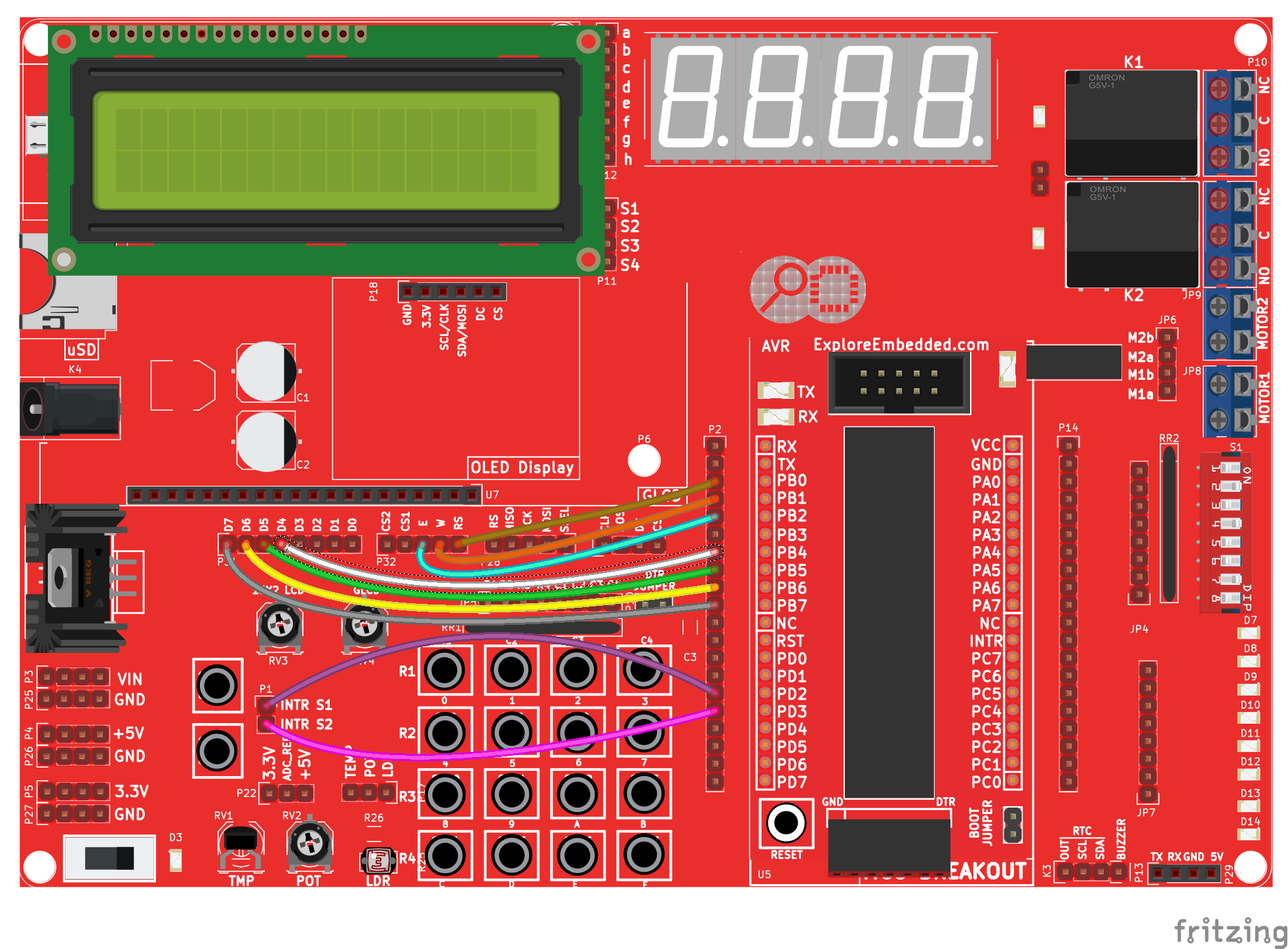
We will connect two switches to the two interrupt pins and show the status on a LCD. The connections are shown in the image below.
Hook Up
The Ultra AVR development board has two switches and also an inbuilt LCD. It is hooked up as shown below:
The Code
Downloads
Code for the tutorial AVR Series

