Difference between revisions of "AVR Timer programming"
| Line 18: | Line 18: | ||
|D7||D6||D5||D4||D3||D2||D1||D0 | |D7||D6||D5||D4||D3||D2||D1||D0 | ||
|} | |} | ||
| − | |||
| − | |||
| − | |||
| − | |||
| − | |||
| − | |||
| − | |||
| − | |||
| − | |||
| − | |||
====TCCR0: Timer/Counter Control Register==== | ====TCCR0: Timer/Counter Control Register==== | ||
{| class="wikitable floatright" style="float:right; background-color:#3DA8BB;" | {| class="wikitable floatright" style="float:right; background-color:#3DA8BB;" | ||
Revision as of 15:02, 18 November 2014
Contents
Basics
Timers come in handy when you want to set some time interval like your alarm. This can be very precise to a few microseconds. Timers/Counters are essential part of any modern MCU. Remember it is the same hardware unit inside the MCU that is used either as Timers or Counter. Timers/counters are an independent unit inside a micro-controller. They basically run independently of what task CPU is performing. Hence they come in very handy, and are primarily used for the following:
- Internal Timer: As an internal timer the unit, ticks on the oscillator frequency. The oscillator frequency can be directly feed to the timer or it can be pre-scaled. In this mode it used generate precise delays. Or as precise time counting machine.
- External Counter: In this mode the unit is used to count events on a specific external pin on a MCU.
- Pulse width Modulation(PWM) Generator: PWM is used in speed control of motors and various other applications.
Timers/Counters in AVR
Timer 0
Timer 0 Registers
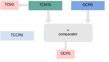
TCNT0: Timer/Counter Register 0
| TCNT0 | D7 | D6 | D5 | D4 | D3 | D2 | D1 | D0 | |||||||
|---|---|---|---|---|---|---|---|---|---|---|---|---|---|---|---|
TCCR0: Timer/Counter Control Register
| TCCR0 | |||||||
|---|---|---|---|---|---|---|---|
| D7 | D6 | D5 | D4 | D3 | D2 | D1 | D0 |
| FOC0 | WGM00 | COM01 | COM00 | WGM01 | CS02 | CS01 | CS00 |
| D6 | D3 | PWM |
|---|---|---|
| WGM00 | WGM01 | Mode |
| 0 | 0 | Normal |
| 0 | 1 | CTC (Clear timer on compare match) |
| 1 | 0 | PWM (Phase correct) |
| 1 | 1 | Fast PWM |


