Difference between revisions of "Explore POV"
| Line 7: | Line 7: | ||
=Solder it!= | =Solder it!= | ||
| − | *Image below shows the layout of various components for the board. It is also printed on the PCB. The image shows reference numbers for all the components. | + | *Image below shows the layout of various components for the board. It is also printed on the PCB. |
| + | ==Component Layout== | ||
| + | The image shows reference numbers for all the components. | ||
[[File:Explore POV layout.JPG]] | [[File:Explore POV layout.JPG]] | ||
*From the table below find out the exact part for the reference number. | *From the table below find out the exact part for the reference number. | ||
| − | + | ==Component List== | |
{| class="wikitable" | {| class="wikitable" | ||
|- | |- | ||
Revision as of 16:37, 6 November 2014
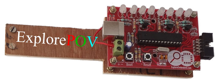
The colorful Persistence Of Vision (POV) kit enables you to create colorful messages in air with just 8 LEDs. This kit is great introduction to soldering and AVR/Arduino Programming. The kit does not require a external programmer, it is self programmable with USB.
Solder it!
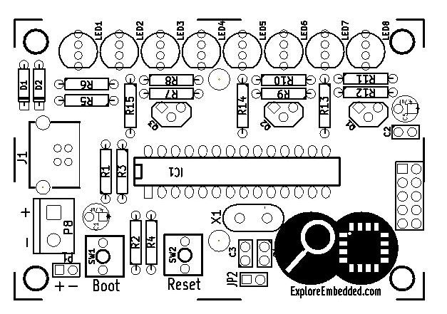
- Image below shows the layout of various components for the board. It is also printed on the PCB.
Component Layout
The image shows reference numbers for all the components.

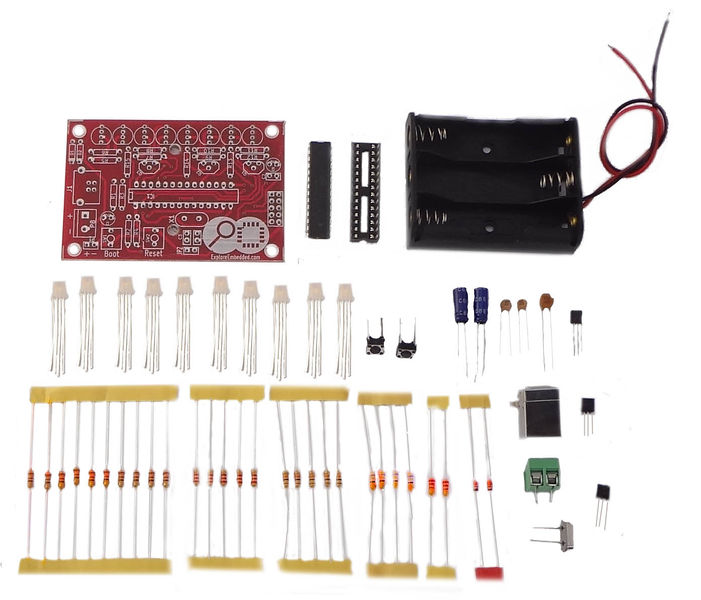
- From the table below find out the exact part for the reference number.
Component List
|
|
|
|
|---|---|---|
|
|
|
|
|
|
|
|
|
|
|
|
|
|
|
|
|
|
|
|
|
|
|
|
|
|
|
|
|
|
|
|
|
|
|
|
|
|
|
|
|
|
|
|
|
|
|
|
|
|
|
|
|
|
|
|
|
|
|
|
|
|
|
|
|
|
|
|
|
|
|
|


